Reports
Project Midan: Developing and Building an Underground Nuclear Test Site in Iran
by David Albright, Sarah Burkhard, Olli Heinonen*, Frank Pabian**, and Andrea Stricker
April 2, 2019
Main report, with Annex I
![]() Download PDF
Download PDF
Annex II
For a summary of the report, click here.
Israeli-seized nuclear archive documentation indicates that Iran had begun the process of establishing an underground nuclear test site and developing the necessary methods to estimate nuclear explosive yield in the early 2000s, an effort known as “Project Midan.”
The project had identified five potential test site locations and was developing approaches, including seismic and other methods, to measure the explosive yield of an underground nuclear test.
Using openly available, corroborating geospatial information, we have identified the likely location (in an area southeast of Semnan) where underground non-nuclear explosives tests were conducted in 2003 as part of developing seismic methods of measuring the yield of an underground nuclear explosive.
It is essential that the International Atomic Energy Agency (IAEA) promptly address all of the information available in the archives, noting that much of this information contradicts Iran’s earlier statements provided during the IAEA’s investigations of the Possible Military Dimensions of Iran’s nuclear program.
Development of nuclear weapon testing capabilities are not compatible with Iran’s undertakings under the Nuclear Nonproliferation Treaty (NPT) and the Comprehensive Nuclear-Test-Ban Treaty (CTBT), and do not support the claim that the nuclear program has always been, and continues to be, entirely peaceful.
It is important for Iran to extend an invitation to the United Nations Preparatory Commission for the Comprehensive Nuclear-Test-Ban Treaty Organization (CTBTO) to assist the IAEA in its investigation, or to ask the Preparatory Commission of the CTBTO to assess separately the status of Iran’s nuclear test plans.
Iran’s Amad Plan called for it to develop and build five nuclear weapons in the first part of the 2000s. 1 It also created an extensive program to construct an underground test site so that Iran would be prepared to test a nuclear explosive by the end of 2003. A portion of the Nuclear Archives seized by Israel in early 2018 contains a variety of information on Iran’s development and implementation of plans for underground nuclear testing, some of which was known before to the IAEA. 2 These findings add more weight to the side of a figurative balance or scale that represents evidence of Iran’s violations of its commitments under the NPT. Under Article II of the NPT, Iran is committed “not to manufacture or otherwise acquire nuclear weapons or other nuclear explosive devices.” Moreover, although Iran has not ratified the CTBT, it did sign the treaty in 1996. Thus, it has an obligation to refrain, in good faith, from acts that would defeat the primary objective of the CTBT, namely the provision, “Each State Party undertakes not to carry out any nuclear weapon test explosion or any other nuclear explosion, and to prohibit and prevent any such nuclear explosion at any place under its jurisdiction or control.” 3 Undertaking a multi-year project to build a nuclear test site hardly qualifies as fulfilling the spirit of that international obligation.
Iran called its underground nuclear test site project “Project Midan,” where midan means “field” in Farsi. It was one of several subprojects housed under Project 110 of the Amad Plan.
Based on available archive information dated to about 2002, Iran would not have met its planned, initial deadline to have the test site ready by the end of 2003. Despite evidence that Iran had made significant progress on being able to test a nuclear explosive underground, the authors could not determine if actual construction of a deep shaft had started. The project had conducted nuclear test site selection, identifying five potential test site locations, and had focused on developing approaches, including seismic and other methods, to measure the yield of an underground nuclear test.
The work on building a test site appears to have halted when the Amad Plan was downsized and reoriented in late 2003. However, given the existence of a post-Amad nuclear weapons program, now determined through analysis of the archive and other information to have existed after 2003, it is logical to assume that Iran continued to maintain preparedness to test and work on developing yield prediction methods after 2003. These efforts would be expected to fall in line with guidelines in an archive document that aimed to integrate and hide certain nuclear weapons activities in civilian programs at universities, and maintain separate secret military programs for other activities that could not be explained by contrived civil or non-nuclear military rationales. 4
The information in the archives is far more extensive than that collected by the IAEA in its past investigations of Iran’s nuclear weapons programs. The new information shows a much more elaborate Iranian effort in developing and building a nuclear test site than known previously.
As we have stated in the findings of our previous reports on the Iranian Nuclear Archives, the IAEA needs to inspect the sites and meet the experts and decision makers involved in Project Amad, including Project Midan. A new issue is that the parties of the CTBT need to look into Project Midan and evaluate the implications for their own work and the scope of the Treaty.
Project Midan Planning in 2000
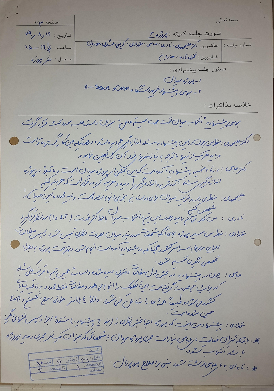
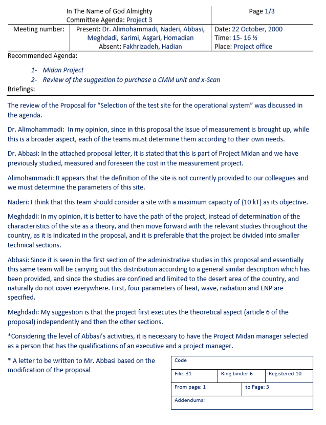
Early planning for Project Midan can be traced in an archive document to late 2000. The proposal for Project Midan was discussed in a committee meeting of Project 3, another codename for Project 110, held on October 22, 2000 at an unidentified “project office.” According to the memo (see Annex 1), in attendance were Drs. Alimohammadi, Naderi, Abbassi, Meghdadi, Karimi, Asgari, and Homadian. Absent were Fakhrizadeh and Hadian. Full names were not listed on the memorandum.
Abbassi appears to be Fereydoon Abbasi-Davani, who became head of Atomic Energy Organization of Iran in 2011. Alimohammadi appears to be Masoud Alimohammadi. 5
Asgari may be Mansur Asgari, who has served as head of the Research and Technology Department of the Organization of Defensive Innovation and Research (SPND). 6 SPND is the follow-on entity of the Amad Plan. According to the U.S. Treasury Department, Asgari was previously a manager under the Amad Plan, where he oversaw Amad Plan projects focused on explosives and exploding bridge wire (EBW) detonators. 7 Naderi may be Brigadier General Mohammed Naderi, now Head of Aerospace Industries Organization.
Fakhrizadeh is likely Mohsen Fakhrizadeh. He was Director of the Amad Plan and is currently the head of SPND.
Specifically, the meeting reviewed the proposal for “Selection of the test site for the operational system,” apparently submitted by Abbasi. The operational system was the term used for the nuclear warhead being developed by the Amad Plan’s Project 110, and the test site was to be developed in an Iranian desert. Alimohammadi and Meghdadi made the bulk of the transcribed comments at this meeting, with one comment by Naderi recommending consideration of a site with a maximum detonation capacity of 10 kilotons as its objective. This yield was also listed in the Nuclear Archive as the yield of each nuclear warhead being built as part of Project 110.
The proposal appears to have been accepted by this committee with some modifications, including apparently Meghdadi’s suggestion to first execute the theoretical aspects (see below). The participants also implied that Abbasi appeared to be somewhat overwhelmed, leading to a recommendation or directive requiring the selection of a Project Midan manager.
Project Midan Timeline and its Relationship to Project 110
An Amad Plan table, which is dated to about 2002 and provides timelines and progress of its major subprojects, lists the start date of Project Midan as December 12, 2000, less than two months after the meeting at the project headquarters discussing the proposal for this project. 8 The table gives an expected completion date of November 16, 2003. At the time the table was prepared, i.e. sometime in 2002, Project Midan was slightly behind schedule, having finished only 38 percent, versus 46 percent, of the planned tasks by that time.
For comparison, according to this table, the start date of Project 110 of the Amad Plan is given as March 20, 2000 and its anticipated completion date is March 17, 2004, by which point five nuclear warheads would be completed, one of which could be tested underground.
Figure 1 shows an early organizational structure of Project 110. As can be seen, the Midan project was one of four main subprojects of Project 110, each of which had a technical committee. The Simulation Project was apparently involved in the theoretical, computer-aided design of a nuclear weapon and had software and hardware subgroups. The Operating System Project appears to have been the largest and was where the development and production of an implosion-type nuclear explosive were taking place. It was also involved in building the nuclear weapons production complex needed to develop, manufacture, and assemble those weapons. The Warhead Project appears to have focused on the design of a nuclear warhead integrated into a re-entry vehicle of a ballistic missile, and construction of critical components associated with that integration and re-entry vehicle. Other tables and charts show that different labelling of the projects was also used, leading to multiple codenames for major projects. So, for example, Project Midan was also codenamed Project 3.19.
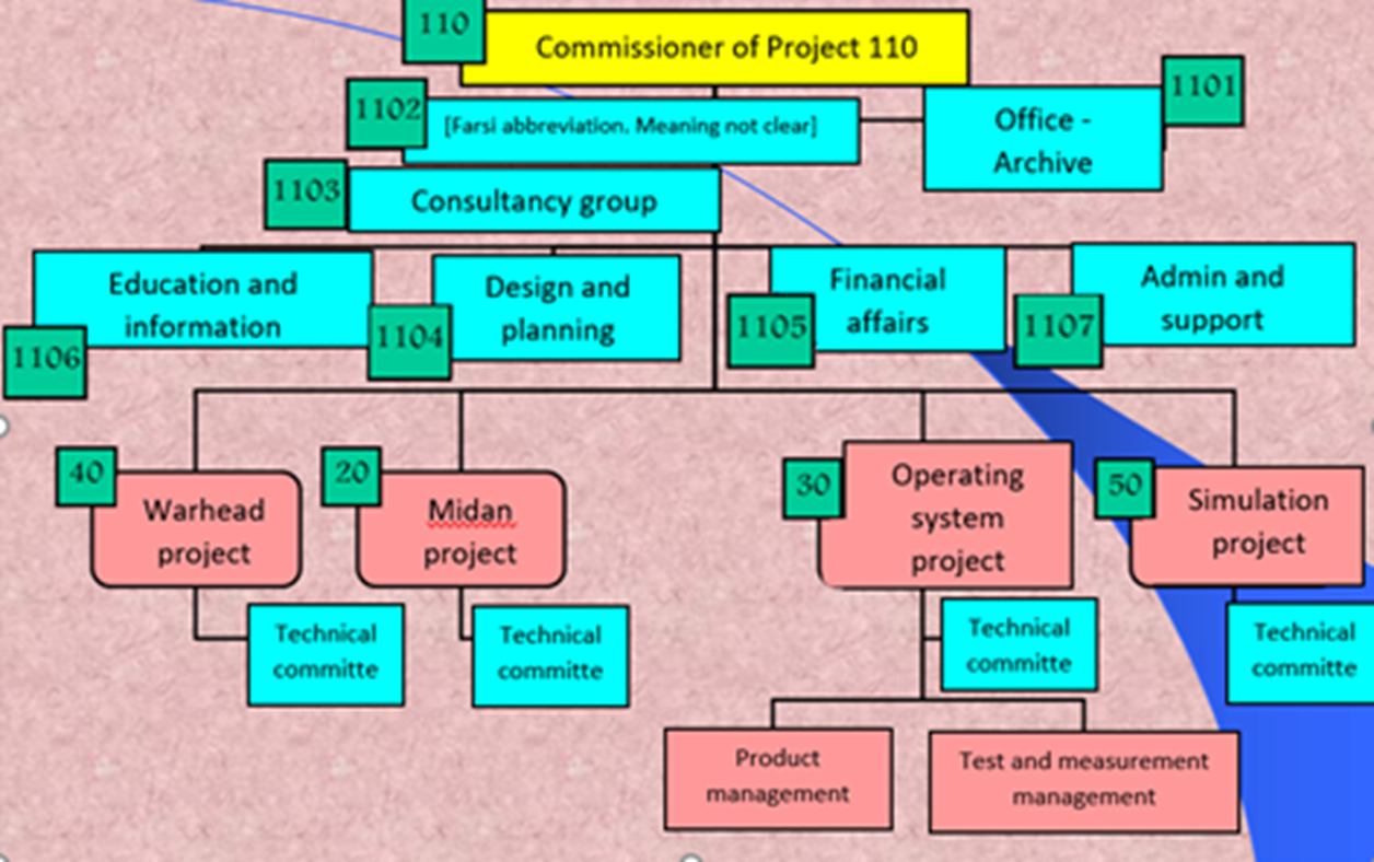
Figure 1. Early organizational chart of Project 110, translated from Farsi. The title of Commissioner can also be translated as Commander.
Steps to a Test Site
Iran’s creation of a test site with at least one deep shaft involved several tasks that can be identified in the documents in the archive. The available information provides a snapshot of the work done in the following areas of constructing a nuclear test site.
Site Selection
Theoretical Calculations
Development of Test Site-Related Equipment and Capabilities, including
- Carrying Device
- Detonation at a Distance
- Yield Evaluation
Site Selection
The archive contains a study dated August 2002, “Site Selection Report,” codenamed Abuzar 1. Figure 2 shows the cover of the report in Farsi.
This subproject developed a methodology for characterizing the regions of interest and picking potential sites, considering population, distance to cities, weather conditions, and several other factors. According to the report, the group developed subject-based maps and prepared an aerial model of desired regions. This allowed the extraction of rural areas from these maps. The group created the various steps to be taken in the site selection process and created a GIS (Geographic Information System) to collect, store, and interrogate the input geospatial data. It cataloged the meteorological stations.
Project Midan picked four potential areas for an underground test site (Figure 3). Based on another document in the archive, five smaller locations within these areas were selected for consideration as candidates for the test site (Figure 4).
Figure 5 shows ground images from the archives of the areas being considered for a nuclear test site. Their remoteness is evident in the images.
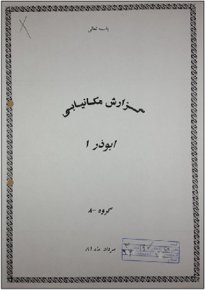
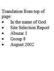
Figure 2. Site Selection Report from the Nuclear Archive by “Group 8,” dated August 2002. See above for additional translations. The stamp is typical of many of the documents in the archive – numbering them and giving a page length. Here, the writing in the stamp is illegible, but on other documents, the stamp contains the file or report number, the ring binder, or page length of the report.
Figure 3. Map from the archive showing four potential areas in Iran for digging an underground nuclear test site outlined in red. One of the outlined areas in the lower right contained two different potential test site locations, making a total of five identified potential test site locations (see figure 4).
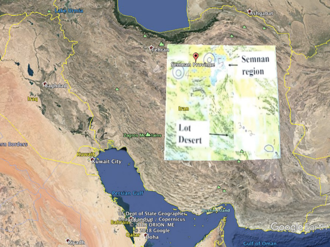
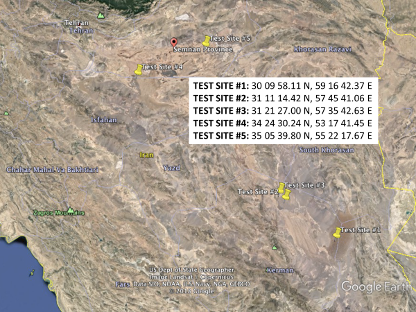
Figure 4. A document in the archive, overlain on a Google Earth image of Iran, also shows the four areas (upper image) being considered for an underground test site. This was refined further to five specific locations, which are numbered 1 through 5 from south to north on the map as received by the Institute (inset, upper image). Another archive document provides the coordinates for these five sites, which the Institute used to geo-locate them in Google Earth (lower image). See Albright and Pabian, “Iran’s Investigation of Possible Underground Nuclear Test Sites in the AMAD Program prior to 2004,” Institute for Science and International Security, May 1, 2018, http://isis-online.org/isis-reports/detail/irans-investigation-of-possible-underground-nuclear-test-sites-in-the-amad/8
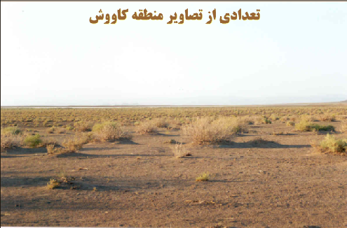
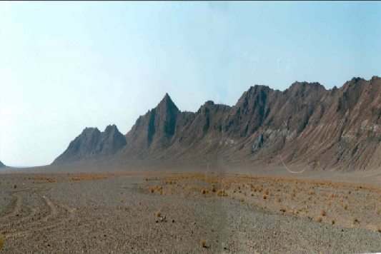
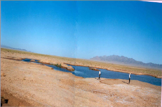
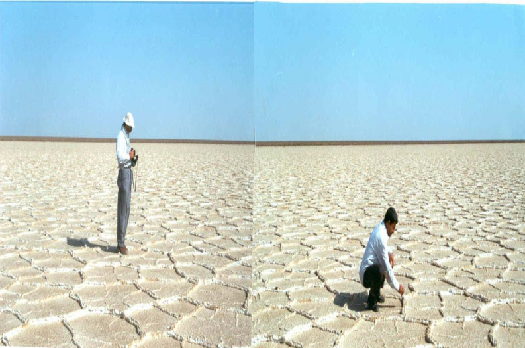
Figure 5. Images from the archive of areas being considered for an underground nuclear test site. The caption on the upper left image from the archive states, “Several Images of the Exploration Region.”
Theoretical Work
The archive has a long report that evaluates the theoretical aspects of building a nuclear test site. 9 The report is authored by the Shahid Chamran Project. 10 It assessed the depth a shaft needed to be for a particular explosive yield, the behavior of the ground and soil during drilling and an explosion, the methods of back filling a shaft after the emplacement of a nuclear device, and software development.
A Power Point presentation from the archives shows details about the software being used by the Shahid Chamran Project. The cover slide is in Figure 6 and is titled “Software Preparation.” The meaning of code 33 is unclear. Another page in this presentation shows that certain, well known commercial software, such as FLAC 3D and 3DEC, were viewed as necessary to the project, and other software, such as ABAQUS, was being considered (Figure 7). According to the web site for the first software, FLAC 3D is a numerical modeling software from Itasca Consulting Group made for geotechnical analyses of soil, rock, groundwater, constructs, and ground support. 11 Such analyses include engineering design, factor of safety prediction, research and testing, and back-analysis of failure. 3DEC, also sold by Itasca, is a three-dimensional numerical modeling code for advanced geotechnical analysis of soil, rock, ground water, structural support, and masonry. 12 3DEC simulates the response of discontinuous media (such as jointed rock or masonry bricks) that is subject to either static or dynamic loading. ABAQUS is a software suite for finite element analysis and computer-aided engineering. It is expected that the project would have adapted this commercially available software to its particular tasks, but details of any of these applications of the software are not available to the Institute.
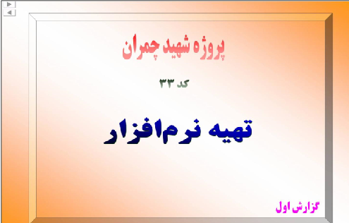

Figure 6. Software Preparation by Shahid Chamran Project for Project Midan, Farsi document from archive and its translation.
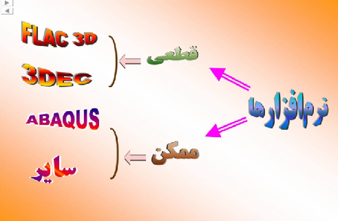
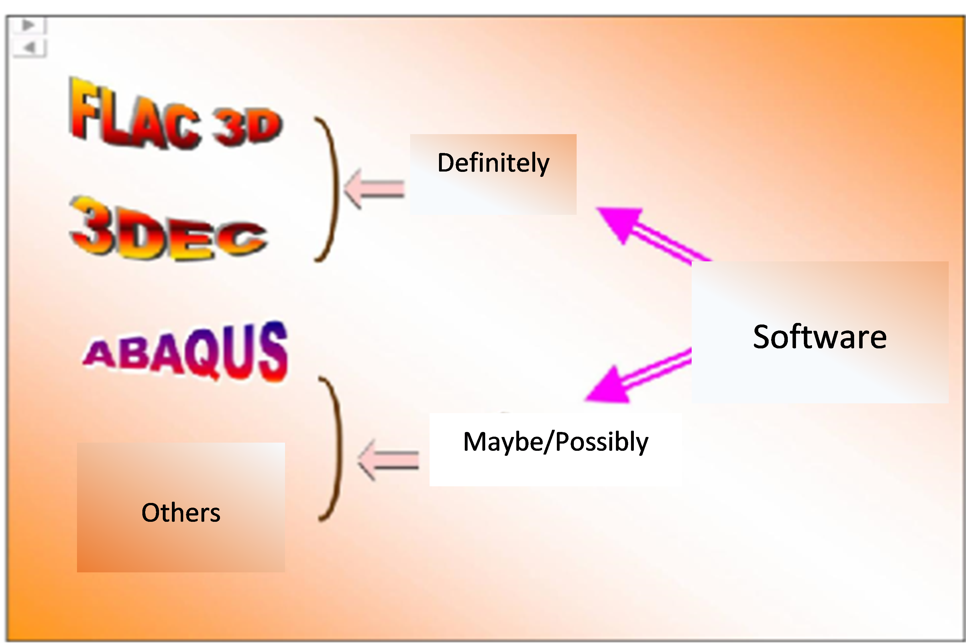
Figure 7. Software considered by Project Shahid Chamran, Farsi document from archive and its translation.
Development of Test Site-Related Equipment and Capabilities
The development and construction of a nuclear test site requires a great deal of equipment and planning. The information available to the authors on this equipment and planning is currently limited. However, a few aspects are known.
Carrying Device. A report in the archive is about designing and manufacturing a cylindrical, metal container for a device and for a carrying device to hold and position the device over a shaft. The archive has pictures of this container and the winch device to hold and lower it. A carrying device schematic from the archive of the system is shown in Figure 8.
Figure 9 shows the container, which is about two meters in length. The diameter is estimated at about one meter across. The dimensions would be sufficient to hold a nuclear device. The archive also has images of the mechanism used to hold and move the container (Figure 10). Figure 11 shows the assembled system. This carrying system shows that Iran was exploring an option to test and manufacture what it needed to do in order to conduct an underground nuclear test.
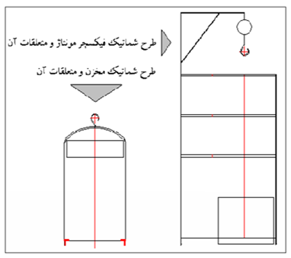
Figure 8. Carrying device schematic from the archive. The two lines in Farsi are: Top: The design schematic for fixture assembly. Bottom: Schematic of the container and its accessories.
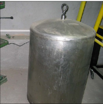
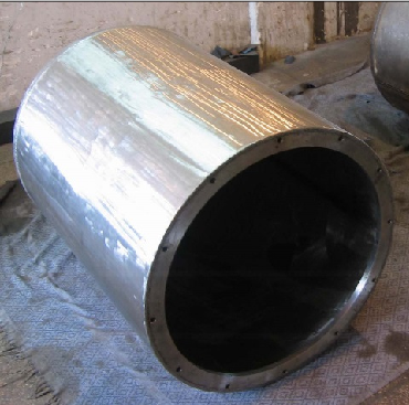
Figure 9. Photos from the archive showing a container to hold a device.
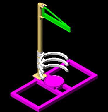
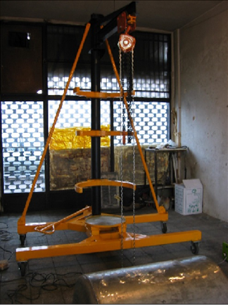
Figure 10. Schematic and manufactured carrying device photo from the archive, the latter with container on side in foreground.
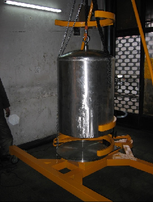
Figure 11. Photo from the archive showing the container and carrying device assembled.
Detonation at a Distance. An underground nuclear explosive would, for safety reasons, be detonated at a distance from a nearby control point. As will be further developed, the IAEA received information from a member that “Iran has conducted a number of practical tests to see whether its EBW [Exploding Bridge Wire] firing equipment would function satisfactorily over long distances between a firing point and a test device located down a deep shaft.” 13 In another report from February 2008, the Agency more specifically said that it “made available documents for examination by Iran and provided additional technical information related to: the testing of high voltage detonator firing equipment; the development of an exploding bridgewire detonator simultaneous firing of multiple EBW detonators; and the identification of an explosive testing arrangement that involved the use of a 400 m shaft and a firing capability remote from the shaft by a distance of 10 km, all of which the Agency believes would be relevant to nuclear weapon R&D.” 14 Iran stated that the documents were fabricated and that the information contained in those documents could easily be found in open sources.
It is unknown if such a control point was ever built. Doing so would imply that a site had been selected. The Institute conducted a search of publicly available commercial satellite imagery of the five potential test site locations, but was unable to detect any evidence of site development activity.
Yield Estimation
Another report in the archive discusses methods to measure the yield of an underground nuclear detonation. Figure 12 shows a presentation slide from the archive of three approaches being pursued by Project Midan to measure the explosive yield, namely seismic, radiochemical, and hydrodynamic methods. As can be seen, at the time the slide was prepared, likely in 2002, the seismic and radiochemical methods had been 100 percent studied and designed, but only 30 and 10 percent implemented, respectively.
In the chart, there are blanks for hydrodynamic methods. Work had evidently just started on this method, mainly involving some literature reviews. Hydrodynamic measurements of underground tests are extremely complicated and typically involve measuring multiple times in real-time the change in the length of a specialized co-axial cable placed near the explosion in the test shaft or a satellite shaft. The cable’s change in length is measured as the growing shock wave crushes and destroys it. This change in length can thus be correlated with the rate of expansion of the shock front, which in turn can be related to yield, assuming that the geology in the area around the explosive is well understood. However, for lower explosive yields, such as what Iran was considering, e.g. ten kilotons, this method can have high uncertainties. Without more information about what, if anything, Iran was doing, this method is not treated in this report in any more detail.
Figure 13 presents another slide that summarizes a variety of reports generated by Project 3.19, another codename for Project Midan, related to measuring yields that were finished by about May 2003. As can be seen, most were related to seismic methods. Some involve theoretical work; others record the results of experiments and the project’s own investigations. The studies also make clear that Iran was leveraging its own, extensive seismic network to study and develop yield estimates for nuclear explosions. Since Iran is in an active earthquake zone, it developed a great number of seismic stations to gauge earthquakes that Project Midan used to aid its effort.
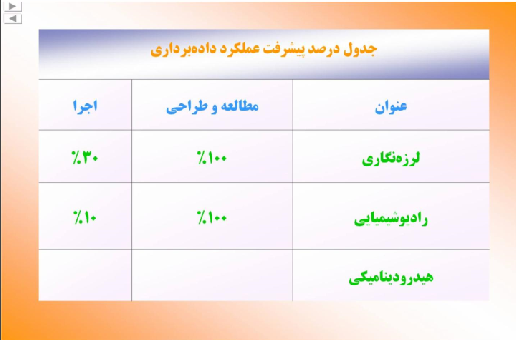
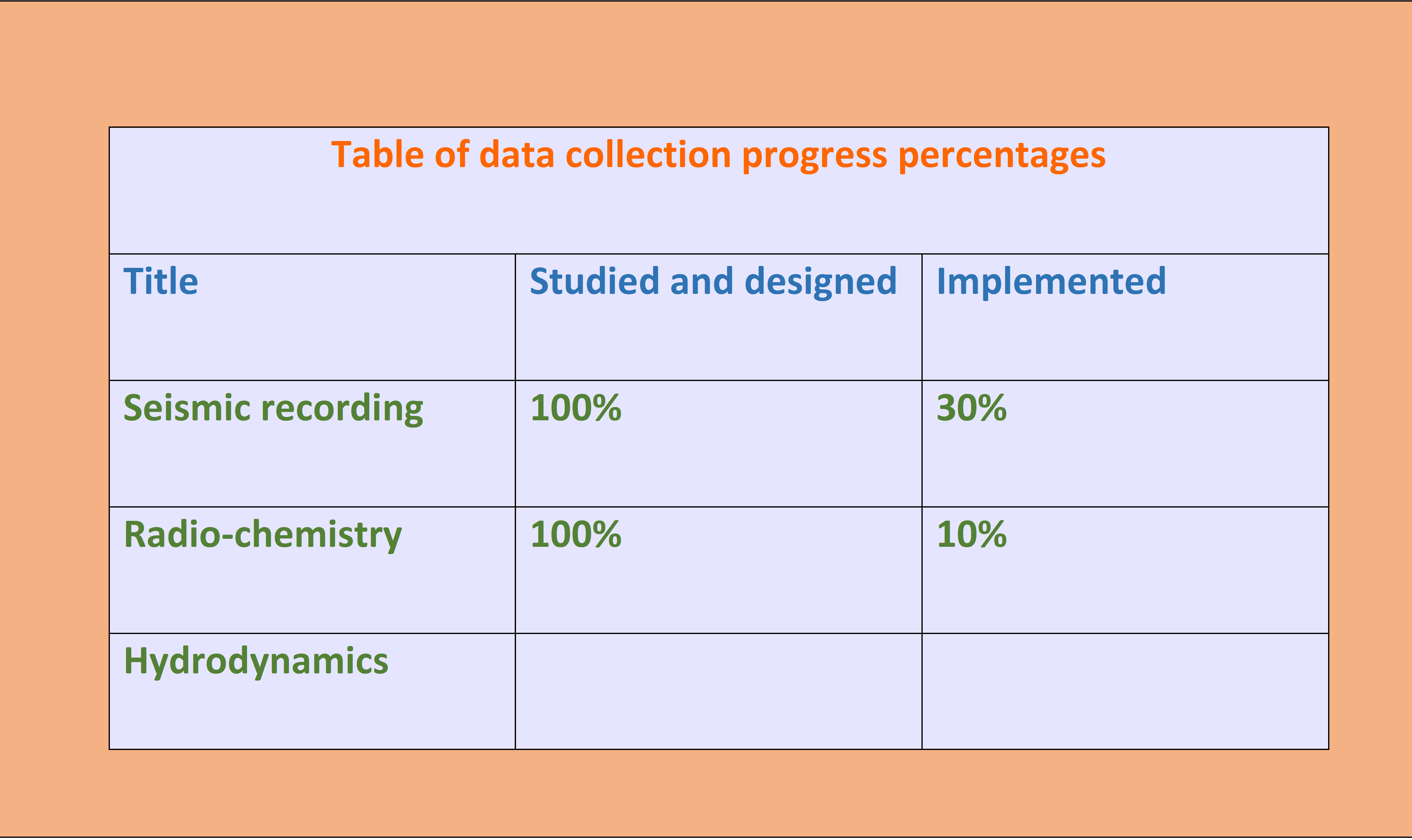
Figure 12. A slide from the archive and its translation on the three methods of yield estimation pursued in Project Midan.

Figure 13. Translated titles of reports from a Farsi document provided by Project 3.19, another codename for Project Midan. The numbered reports appear to be progress or research reports produced by subprojects of Project Midan (see below).
Radiochemical Methods of Yield Prediction
Radiochemical methods provide some of the most reliable ways of estimating yield. This can involve measurements taken soon after an explosion to seek the spectrum of emitted radioactive elements, or chemical sampling in the resulting cavity or collapsed volume of the nuclear test. Post-shot chemical sampling of the area near the explosion can be conducted by drilling a borehole diagonally into the area of the detonation and taking a variety of samples at different depths and locations. With extensive knowledge of the nuclear explosive and the resulting explosion, e.g. size of the resulting cavity, analysis of the total amount of nuclear reactions is possible, allowing a yield prediction via drilling and sample taking.
Figure 14 shows a cover slide from the Nuclear Archive on radiochemical methods of estimating the yield. However, the Institute did not obtain any other documents detailing this project’s work on developing this method, including plans and equipment to take aerosol radioactive samples or drill back into the area of the detonation and take samples.

Figure 14. Slide from archive and translation.
The Institute did receive several slides from the archive, essentially images with English captions and Farsi annotations, that show Iran was using information from other nuclear weapons programs to explore this topic. Figure 15 shows several images in the archive with Farsi annotations. The Institute located these images in a 1999 report in the newsletter of the Indian Bhabha Atomic Research Center titled, “Post Shot Radioactivity Measurements on Samples Extracted from Thermonuclear Test Site.” 15 The article describes the procedures followed to collect and analyze a set of fission and activation products near the detonation point and the resulting radiochemical analysis to estimate the yield of the 1998 purported thermonuclear test at the Pokhran underground test site in India. As can be seen in Figure 15, some of the charts have Farsi written on them. The reprinted figures summarize a reasonable method to drill back into the test site, take multiple core samples at different depths and locations, analyze a set of fission products to determine their activity per gram of sample, and integrate over the active zone to arrive at a total number of fissions, which can be related to total energy release or yield.
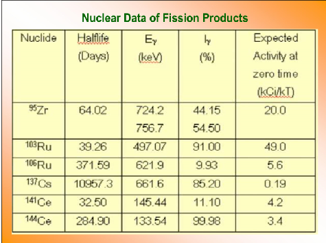
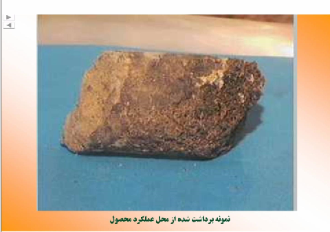
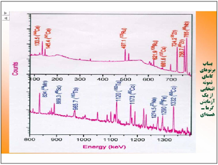
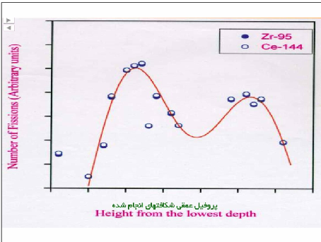
Figure 15. Figures from the archives annotated in Farsi, reprinted from a 1999 BARC report (see footnote 15) estimating the explosive yield of an underground test of a thermonuclear device in India. In the figure in the upper left, the table contains what the report states are the fission products used in the Indian estimate of yield. On the upper right, the Farsi text reads: “Collected sample from locations of [fission] products.” In the original report, the caption is: “Photograph of a typical rock sample,” and the text of the report states that it is a core sample collected from near the detonation point. In the figure at lower left, the Farsi text reads: “Chart for gamma radiation of the selected or typical sample of the thermonuclear test,” showing the gamma ray peaks of fission and activation products in the sample. On the bottom right graph, the original caption is “Depth profile of fission products,” which refers to the radioactivity of high-yield, refractory fission products, namely zirconium 95 and cerium 144 (which have no gaseous precursors that can escape and do not form volatile compounds), and were collected in samples taken at various depths in the immediate area of the nuclear blast. The graph shows a large variation in the number of fissions in the vertical direction, but an identical distribution pattern of these two fission products (the data points for zirconium and cesium are overlapping). The latter implies that the measurements were reliable.
Seismic Methods
Figures 12 and 13 make clear that Iran had made the most progress on seismic methods to measure the yield, where by the time of the slide, it assessed it was 30 percent finished. Project Amad likely had help on developing seismic methods, since Iran is in an earthquake zone and had built extensive skills and experience in seismology. The open literature on seismic methods for yield predictions was also much more extensive than that of the other methods discussed here, partly because of the work surrounding the development of verification methods for the Comprehensive Test Ban Treaty. This work was quite detailed and discussed openly in the literature and at government fora focused on the CTBT and its verification.
Beyond the theoretical seismological work mentioned in Figure 13, Iran also conducted seismic experiments using high explosives. A title page of a document related to preliminary work to develop seismic detection methods to predict the explosive yield is shown in Figure 16.
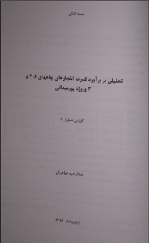
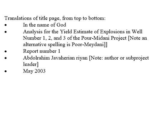
Figure 16. Archive document on developing yield estimates via seismic methods.
The author listed on the document is Abdulrahim Javaherian riyan. There is an Abdolrahim Javaherian, Ph.D, who is currently Professor of Geophysics, Department of Petroleum Engineering at Amirkabir University of Technology. A literature search by Mark Gorwitz produced an extensive number of his scientific publications on seismology.
The tests involved the detonation of three high explosions, ranging from 0.5 to 4.62 tons of TNT. Figure 17 is a page from this report that has the locations, dates, and times of high explosive tests in what are called wells 1, 2, and 3.
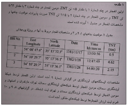
Figure 17. Page from report in archive on high explosive tests showing the time, location, and magnitude of a high explosive test on February 6, 2003 and two tests on April 17, 2003.
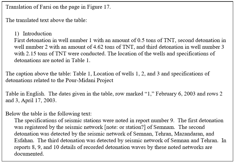
Figure 18 shows the locations of the Pour Midani high explosive tests in Iran and the area of the Chah Shirin mountains. Their location is near the Semnan Space Launch Center, which was built soon after these high explosive tests.
Figure 19 contains two ground photos from the archive of the area of one of the high explosive tests, which consists of an alluvial plain in this very remote area of Iran.
Figure 20 shows the location of the high explosive tests relative to the five potential underground nuclear test sites.
Figure 21 correlates one of the ground images with 3D terrain on Google Earth, which is observed when the cursor for ground-level view is placed on the coordinates given in the Nuclear Archive. This supports that the ground photos were taken, and the tests were conducted, in close proximity to the provided coordinates.
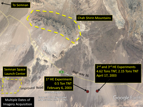
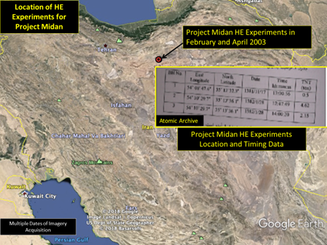
Figure 18. Location of the high explosive test sites near the Chah Shirin mountains.
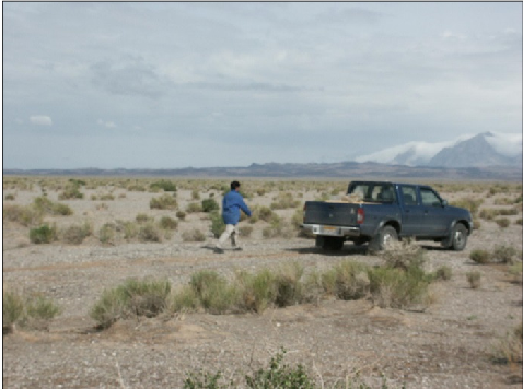
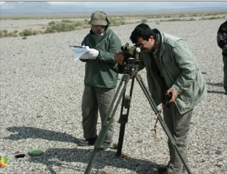
Figure 19. Two archive images from the area of the Pour Midani high explosive tests.
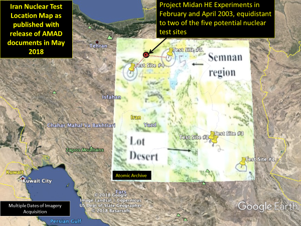
Figure 20. The location of the high explosive tests relative to the potential nuclear test sites.
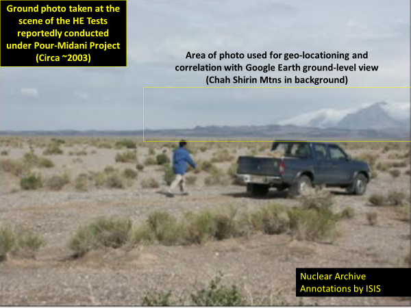
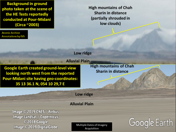
Figure 21. Correlating one of the ground photos (top) to Google Earth 3D perspective terrain of the area generated from the Nuclear Archive document’s geo-coordinates (bottom).
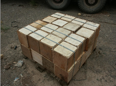
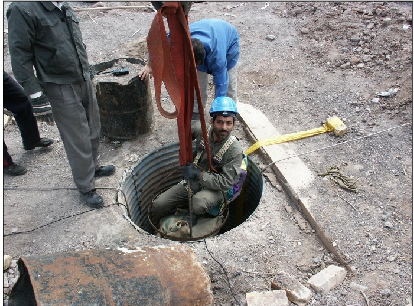
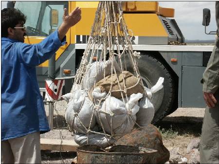
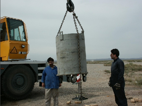
Figure 22. Archive images of high explosive tests. High explosives in upper left image. High explosive shaft (upper right). Possibly fill material for the shaft (bottom left) and capping it with a concrete plug, prior to detonation (bottom right).
The seismic high explosive experiment involved placing the high explosives down a shaft. The shafts were 30 meters deep. Figure 22 shows four ground images from the archive of what appears to be the preparations for a below-grade high explosive test.
After the detonations, seismic waves propagated outward were recorded at local seismic stations. Overall, Iran appears to have well documented the high explosive events. The Iranian report (Figure 17) states that the explosions were detected at a few local seismic stations up to a few hundred kilometers from the blast. The Iranian document on the high explosive tests states: “In reports 8, 9, and 10 details of recorded detonation waves by these noted networks are documented.” These reports appear to be the same ones listed in the table of Project Midan reports in Figure 13, bullet 12, which have to deal with “recording waves produced by detonations.” Obtaining access to these documents could be helpful in follow-up efforts to investigate this issue.
It is not surprising that several stations, as distant as Esfahan, recorded the explosions, particularly the largest test. Figure 23 shows a recent map of the many seismic stations in Iran, where the general location of the high explosive tests is marked on the maps.
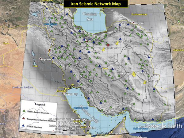
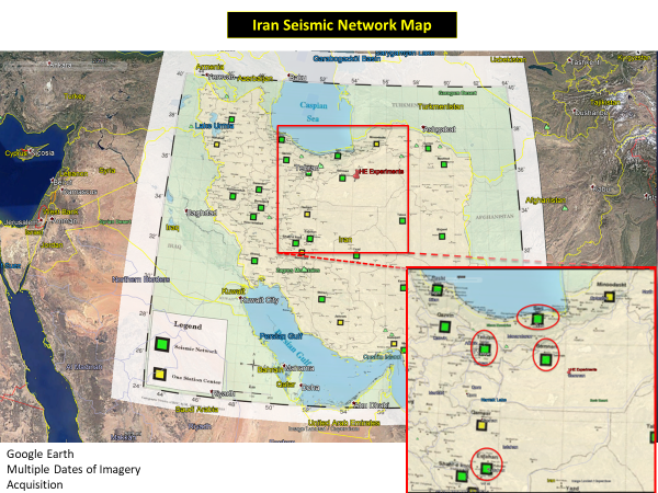
Figure 23. Seismic stations in Iran overlain on Google Earth images. The top image shows a recent map of Iran’s seismic network and the location of the high explosive tests and the five potential underground nuclear test sites. The bottom image is a map of seismic networks of the Iranian Seismological Center. Map © Cartography Division of IRSC, by M. Dezvareh, September 2015. The inset encircles in red the seismic networks listed in the Nuclear Archive that picked up the 2003 explosive tests, which were part of preliminary experiments under Project Midan: Semnan, Tehran, Esfahan, and Mazandaran (Sari is in the Mazandaran province).
The Institute also looked for seismic evidence of these explosions outside of Iran. The closest non-Iranian station was in Turkmenistan at a distance of about 500 kilometers from the blast points. Seismic events are recorded on the websites of the International Seismological Center (IDC) ( http://www.isc.ac.uk/iscbulletin/search/catalogue/ ) and the U.S. National Earthquake Information Center (NEIC)
(https://earthquake.usgs.gov/earthquakes/search/). However, these data do not indicate any seismic event that could be associated with these three explosions.
This result is not surprising given the distances to the nearest station outside Iran, the geology, the time of the day (high noise), and the presence of standard seismic equipment not specialized in detecting high-frequency signals from local explosions. In any case, the Iranians were likely conducting these relatively small yield tests to see how the detonations would record locally.
Since 2010, the CTBTO, the implementing arm of the CTBT, has operated a high capability array station, Alibeck in Turkmenistan, 500 kilometers from the Iranian test site. This array would be expected to provide excellent coverage.
Google Earth and Bing did not have any high resolution images of the area of the high explosive tests near the time of the tests in 2003. We obtained September 9, 2016 and March 15, 2018 images from Digital Globe to try to see any lingering evidence of the tests. Part of the motivation for obtaining imagery is that tracks in the desert can last for decades.
However, the high explosive tests were conducted in the vicinity of the Semnan Space Launch Center, more officially called the “Imam Khomeini Space Center (Semnan).” Construction of this launch center reportedly started in 2003 and it continues to operate. Further complicating our analysis, in the images, we identified another area near the Space Center and closer to the location of the Project Midan high explosive tests, which we call the “Semnan Military Proving Ground,” an area for conducting a variety of testing of military explosives and mobile missile systems. We could not find any public record of such a military proving ground located east of the Semnan Space Launch Center, making this identification the first public one (see Figure 24 and Annex 2).
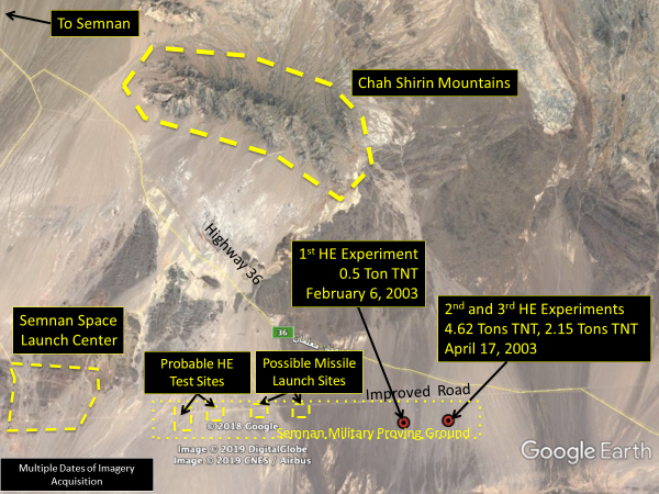
Figure 24. Overview of test site locations, the Semnan Military Proving Ground, and the Semnan Space Launch Center.
We believe that we have identified the location of the first nuclear related high explosive test (0.5 tons of high explosives or HE) as a circular mound of disturbed earth located at the precise location given in the Nuclear Archive document, “Analysis for the Yield Estimate of Explosions in Well Number 1, 2, and 3 of the Pour-Midani Project” (see Figure 17). This location looks the same in both the 2016 and 2018 images (Figure 25). However, we could not discount changes earlier than 2016 and following such a test in 2003.
The second site (reportedly involving tests with 4.62 and 2.15 tons of high explosives) could not be confidently identified. Nonetheless, areas of ground scraping could be identified at the end of a vehicle track that begins at an improved road and is within 200 to 300 meters of the geolocation given for the second and third nuclear related tests (Figures 26 and 27). The fact that additional new ground scraping has taken place after 2016 is evidence that the area is still being used as part of what we have labelled as the Semnam Military Proving Ground. A small possible camp or support area remnant can also be observed located about 650 meters north of the Nuclear Archive’s geolocation for the second and third high explosive tests (Figure 27).
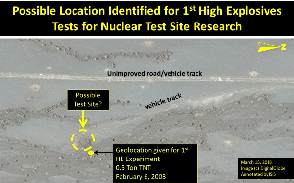
Figure 25. Possible location of first high explosive test on February 6, 2003.
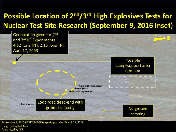
Figure 26. Area of second and third high explosive tests.
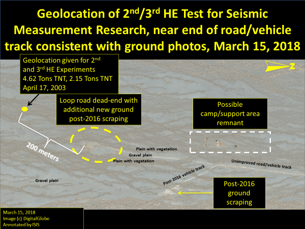
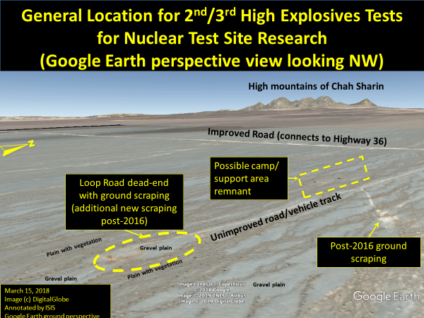
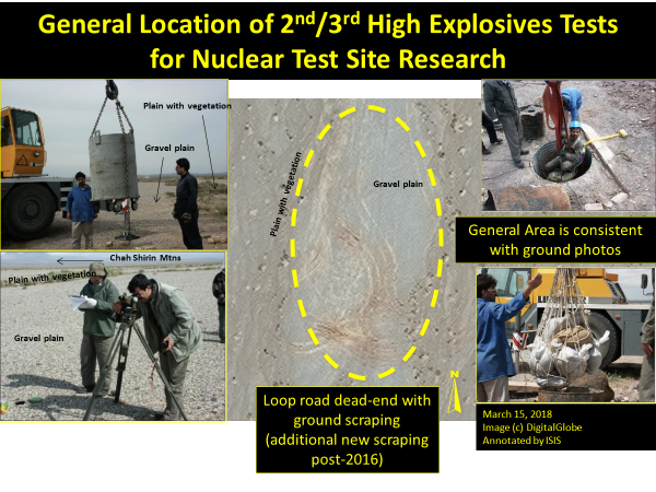
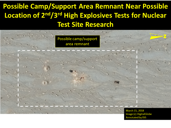
Figure 27. Geolocation of second and third high explosive tests and their correlation with ground imagery from the Nuclear Archive and recent commercial satellite imagery.
Comparison of the terrain in the ground photos of the Project Midan high explosive test activities provides excellent correlation with what can be observed at the geolocations on commercial satellite imagery of the site and in perspective views generated with Google Earth, leaving no doubt that the geolocations of the nuclear related high explosive tests found in the Nuclear Archive are quite accurate (Figure 27). Despite the thirteen plus years since the high explosive tests occurred in early 2003, using what high resolution imagery was available, we do believe that we were able to locate the first test site, but we are not confident that the second and third test site(s) can be similarly located.
Each test area of the Semnan Military Proving Ground has its own dedicated bunkered structure, probably for fire control and diagnostics located along the improved road at various intervals from one to three kilometers apart. As can be seen in Annex 2, we have identified two high explosives test areas and two “probable” missile test launch sites. The Iranians utilized two such test areas further east along the improved road, where the geolocations in the chart place the high explosive test locations about 1.2 kilometers directly south of the improved road where a bunkered structure is present.
IAEA
The IAEA obtained information about Iran’s efforts to build an underground nuclear test site, but this information was not as detailed as that in the archive. The IAEA had information indicating that in 2002 and 2003, “Iran may have planned and undertaken preparatory experimentation relevant to testing a nuclear explosive device.” 16 Iran has not responded to the IAEA’s questions in this area.
According to the 2011 IAEA safeguards report on the issue of building a test site and carrying out a test: 17
The Agency has information provided by a Member State that Iran may have planned and undertaken preparatory experimentation which would be useful were Iran to carry out a test of a nuclear explosive device. In particular, the Agency has information that Iran has conducted a number of practical tests to see whether its EBW [exploding bridge wires] firing equipment would function satisfactorily over long distances between a firing point and a test device located down a deep shaft. 18 Additionally, among the alleged studies documentation provided by that Member State, is a document, in Farsi, which relates directly to the logistics and safety arrangements that would be necessary for conducting a nuclear test. The Agency has been informed by a different Member State that these arrangements directly reflect those which have been used in nuclear tests conducted by nuclear-weapon States.
In particular, as discussed earlier, the IAEA received conceptual development information about a 400 meter-deep shaft with a control center 10 kilometers away. The information reportedly showed the placement of a high voltage power generator. The information also showed the development of a remote system for firing an object in the 400 meter-deep shaft. However, the information did not state that it is about the testing of a nuclear explosive device; that conclusion is inferred. 19
Findings and Recommendations
The archive documentation shows an Iranian program to build a nuclear test site in the early 2000s that was further along than previously thought, at least publicly. But it also raises questions. Did digging on a deep shaft commence? Where is the carrying device that is in the pictures? What diagnostic equipment was built and where is it today? Is there a group of Iranian experts dedicated to maintaining a capability to build a nuclear test site while honing its skills at instrumenting that test and hiding the site from detection? These questions deserve to be answered.
The information supports the earlier findings that Iran violated its commitments under the Nuclear Non-Proliferation Treaty and a new finding that Iran’s actions were not compatible with the spirit of its commitments as a signatory of the Comprehensive Test Ban Treaty. Moreover, every quarter since the implementation of the JCPOA in early 2016, the IAEA has not yet reported that it has been able to determine if Iran’s nuclear program is devoted to peaceful purposes only. In general terms, the archive information supports that Iran continued some parts of its nuclear weapons program post-Amad. The IAEA, the Preparatory Commission for the CTBTO, and their member states need to understand how far Iran’s underground testing program progressed and its status today.
As we have recommended throughout this effort to understand the archives, the new information derived from the Iranian Nuclear Archive adds more urgency to efforts to: create a full correct and complete history of Iran’s nuclear weapons efforts; obtain answers from Iran about the fate of the equipment, material, technology, and personnel discussed in the archive; and more broadly, to characterize the Amad Plan and its successor programs.
Iran may have had and still may have until now undeclared nuclear activities. It is therefore essential that the IAEA Board of Governors requests the Secretariat to verify on an expedited basis the existence of the documents in the archive, their contents, and related equipment to ensure that all nuclear material and activities have indeed been declared to the IAEA, and all non-peaceful activities have been terminated and relevant capabilities dismantled.
The IAEA should be asked to verify sites, locations, facilities, documentation, equipment, and materials mentioned in the archive, question personnel involved, and report on that work. Iran should be urged to cooperate fully in these investigations.
The Preparatory Commission for the CTBTO should look at Iran’s past nuclear testing activities. Via consultation and clarification, and requests for on-site visits, the Preparatory Commission should seek to determine the history and status of Iran’s nuclear weapons testing program. Such an effort from Iran would support its claims that its nuclear program is peaceful.
The U.S. government should seek to identify those individuals that played a critical role in the nuclear weapons program and ascertain their activities today. For those still active in Iranian nuclear and missile programs, or linked to successor entities of the Amad Plan, the United States should continue to designate and sanction them as it recently did 14 individuals and 17 entities linked to Iran’s past nuclear weapons efforts and possibly ongoing activities under SPND. 20 These initial nuclear-related designations by the United States for those found in the Nuclear Archive is an important step in acting on the information from the archive seized over one year ago.
Annex 1 “Selection of the test site for the operational system,” Minutes of Committee Meeting, October 22, 2000. English translation follows
[*] Olli Heinonen is Former Deputy Director General of the IAEA and head of its Department of Safeguards. He is a Senior Advisor on Science and Nonproliferation at the Foundation for Defense of Democracies.
[**] Frank Pabian is a retired Los Alamos National Laboratory (LANL) Fellow from both the Global Security and Science-Technology-Engineering Directorates, most recently in the Geophysics Group, Earth and Environmental Sciences Division, with 45 years of experience in satellite remote sensing for nuclear nonproliferation. He also served in the 1990s as a United Nations Nuclear Chief Inspector in Iraq for the IAEA.
1. “Amad” in Farsi means a logistical organization, mostly military in nature. ↩
2. IAEA Director General, Implementation of the NPT Safeguards Agreement and relevant provisions of Security Council resolutions in the Islamic Republic of Iran, GOV/2011/65, November 8, 2011, http://www.isis-online.org/uploads/isis-reports/documents/IAEA_Iran_8Nov2011.pdf. See also below for a more thorough discussion of the IAEA’s previous knowledge. ↩
3. Article I.1. of the CTBT. ↩
4. The document can be found in David Albright, Olli Heinonen, and Andrea Stricker, “Breaking Up and Reorienting Iran’s Nuclear Weapons Program: Iran’s Nuclear Archive Shows the 2003 Restructuring of its Nuclear Weapons Program, then called the AMAD Program, into Covert and Overt Parts,” October 29, 2018, http://isis-online.org/isis-reports/detail/breaking-up-and-reorienting-irans-nuclear-weaponsprogram/8 ↩
5. Alimohammadi was assassinated in 2010. ↩
6. U.S. Treasury Department, “U.S. Government Sanctions Organizations and Individuals in Connection with an Iranian Defense Entity Linked to Iran’s Previous Nuclear Weapons Work,” Press Release, March 22, 2019, https://home.treasury.gov/news/press-releases/sm634 ↩
7. Ibid. ↩
8. Table titled “Plan Amad,” listing major subprojects, start and end dates, and project progress. In Farsi. Undated, but based on information in the table on the progress of subprojects, it appears to have been prepared in 2002. ↩
9. This document was viewed by Albright in Tel Aviv, January 27, 2019. ↩
10. Mostafa Chamran Save’ei (Persian: مصطفی چمران ساوهای) was an Iranian physicist, politician, commander, and guerrilla who served as the first defense minister of post-revolutionary Iran and as a member of parliament. He was killed during the Iran/Iraq War. Dr. Chamran published extensively, and a number of facilities carry his name, including at the Atomic Energy Organization of Iran. There is a Shahid Chamran Group that is a subgroup of SPND that was recently designated by U.S. Treasury. This group’s work included studies on electron acceleration and mass transfer. This group also conducted research for SPND related to electromagnetics, pulse power, and wave generation. See: “U.S. Government Sanctions Organizations and Individuals in Connection with an Iranian Defense Entity Linked to Iran’s Previous Nuclear Weapons Work,” https://home.treasury.gov/news/press-releases/sm634 ↩
11.https://www.itascacg.com/software/flac3d t ↩
12. https://www.itascacg.com/software/3dec ↩
13. IAEA Director General, Implementation of the NPT Safeguards Agreement and relevant provisions of Security Council resolutions in the Islamic Republic of Iran, GOV/2011/65, November 8, 2011, http://www.isis-online.org/uploads/isis-reports/documents/IAEA_Iran_8Nov2011.pdf ↩
14. IAEA Director General, Implementation of the NPT Safeguards Agreement and relevant provisions of Security Council resolutions 1737 (2006) and 1747 (2007) in the Islamic Republic of Iran, GOV/2008/4, February 22, 2008, https://www.iaea.org/sites/default/files/gov2008-4.pdf ↩
15. S.B. Manohar, B.S. Tomar, S.S. Rattan, V.K. Shukla, V.V. Kulkarni and Anil Kakodkar, “Post Shot Radioactivity Measurements on Samples Extracted from Thermonuclear Test Site,” BARC Newsletter, No. 186, July 1999. Available at https://fas.org/nuke/guide/india/nuke/990700-barc.htm ↩
16. IAEA Director General, Final Assessment on Past and Present Outstanding Issues regarding Iran’s Nuclear Programme, GOV/2015/68, December 2, 2015, paragraph 66,
http://isis-online.org/uploads/isis-reports/documents/IAEA_PMD_Assessment_2Dec2015.pdf ↩
17. IAEA Director General, Implementation of the NPT Safeguards Agreement and relevant provisions of Security Council resolutions in the Islamic Republic of Iran, GOV/2011/65, November 8, 2011, http://www.isis-online.org/uploads/isis-reports/documents/IAEA_Iran_8Nov2011.pdf ↩
18. From the table on last page of the 2011 safeguards report: “Presence of 400m Shaft in Test Sketch.” ↩
19. IAEA Director General, Implementation of the NPT Safeguards Agreement and relevant provisions of Security Council resolutions 1737 (2006) and 1747 (2007) in the Islamic Republic of Iran, GOV/2008/4, February 22, 2008, https://www.iaea.org/sites/default/files/gov2008-4.pdf ↩
20. U.S. Department of Treasury, “U.S. Government Sanctions Organizations and Individuals in Connection with an Iranian Defense Entity Linked to Iran’s Previous Nuclear Weapons Effort,” Press Release, March 22, 2019, https://home.treasury.gov/news/press-releases/sm634 ↩
 email us
 twitter