Reports
New Extension to the Chashma Plutonium Separation Facility
by Neil Hyatt[1] and Sarah Burkhard
November 30, 2020
Satellite imagery available on Google Earth show that an interesting and previously undocumented expansion of the nuclear fuel reprocessing / plutonium separation facility at the Chashma nuclear complex in Pakistan began in mid-2018. The extension’s exterior appears completed as of September 2020. The reprocessing plant was first identified by ISIS in 2007 and considered to be potentially operational in 2015 2,3 The development of this extension and allied facilities at the Chashma reprocessing plant are analysed herein.
Background
Pakistan first developed plans to acquire reprocessing technology in the 1960s. In 1972, Pakistan entered into talks with Saint Gobain Technique Nouvell (SGN) of France to procure a reprocessing facility with a design capacity of 100 tons of heavy metal (tHM) per year.4 A contract for a basic design was signed in 1973, and another for a detailed design in 1974, but France eventually cancelled the deal in 1978, due to U.S. government concern that the facility would benefit Pakistan’s nuclear weapons program. However, construction of the reprocessing facility had already commenced and a considerable amount of design and specification information had already been transferred by SGN to the Pakistan Atomic Energy Commission (PAEC). Pakistan stated its intent to complete the facility, but failed to find another supplier.5 Construction stalled. Historic imagery shows that the plant became overgrown and remained dormant for many years. No further progress was apparently made until construction resumed some time between 2000 and 2002.6 In the interim, Pakistan built the smaller New Labs reprocessing facility at PINSTECH, near Islamabad, to reprocess spent fuel from the unsafeguarded Khushab I heavy water reactor. In parallel to the resumption of construction at Chashma, an expansion at PINSTECH began which appeared to be a second reprocessing facility, roughly doubling the reprocessing capacity at that location.7
The investment in additional reprocessing capabilities occurred in parallel with the construction of three additional unsafeguarded heavy water reactors at the Khushab site from 2001 – 2015, Khushab II, III, and IV. All four Khushab reactors are believed to be operational and dedicated to plutonium production.8 With the additional Khushab reactors, located approximately 80 km east from Chashma, and 200 km from the New Labs facility, the need for a larger plutonium separation capability is credible.
Additionally, at the Chashma site, four 300 MWe pressurised water reactors (CHASNUPP 1 – 4) were constructed and brought into operation from 2000 – 2017, with a fifth unit planned.9 These reactors operate under IAEA safeguards. A 2019 PAEC slide presentation to an IAEA conference stated an intention for on-site dry storage of the spent nuclear fuel from the CHASNUPP reactors.10 It stated that currently, all spent fuel from Pakistan’s safeguarded reactors is in wet storage. An associated graphic indicates with a question mark that the decision whether to pursue reprocessing of the spent fuel had not yet been made. Already a few years prior, in 2014, a PAEC slide presentation had stated that after dry and wet storage, the fate of the spent fuel had “yet to be decided.”11
Figure 1, a May 2020 Google Earth satellite image, gives an overview of the Chashma nuclear complex, highlighting the four CHASNUPP reactor units and the reprocessing plant. Also highlighted is the likely Kundian fuel production plant (the Kundian Nuclear Complex 1) which manufactures fuel for the KANUPP reactor.
The majority of the apparent construction of the Chashma reprocessing plant and associated facilities lasted from 2002 to 2013 and was documented by ISIS.12 For the reasons given above, the plant’s primary purpose is assumed to be plutonium separation from unsafeguarded heavy water reactors at the Khushab site. The plant may have become operational around 2015, 13 but it is unknown whether the facility continued to operate during the most recent and possibly still on-going constructions.
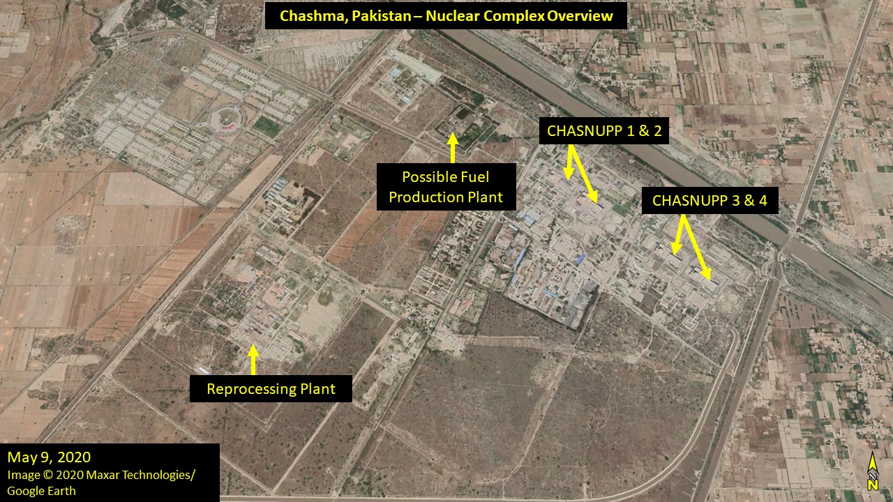
Figure 1. Overview of the Chashma Nuclear Complex.
Figure 2 shows the reprocessing facility in 2017; a tall, windowless building of concrete construction, and an associated high stack. The building is contained within a security fence, which is further secured by three outer perimeter fences. These signatures are consistent with those expected of such a facility, and open source information locating a reprocessing plant at Chashma14, as previously reported by ISIS.15 Of note is a 5 x 3.5 meters engraved flag of Pakistan at the front personnel entrance to the Chashma facility, first apparent in imagery dated 21 November 2017, which evidently communicates the national significance of the facility. The site further features an ornamental garden, similar to one near New Labs at PINSTECH (see inset in Figure 2). The garden is one of several visible parallels between the two sites.
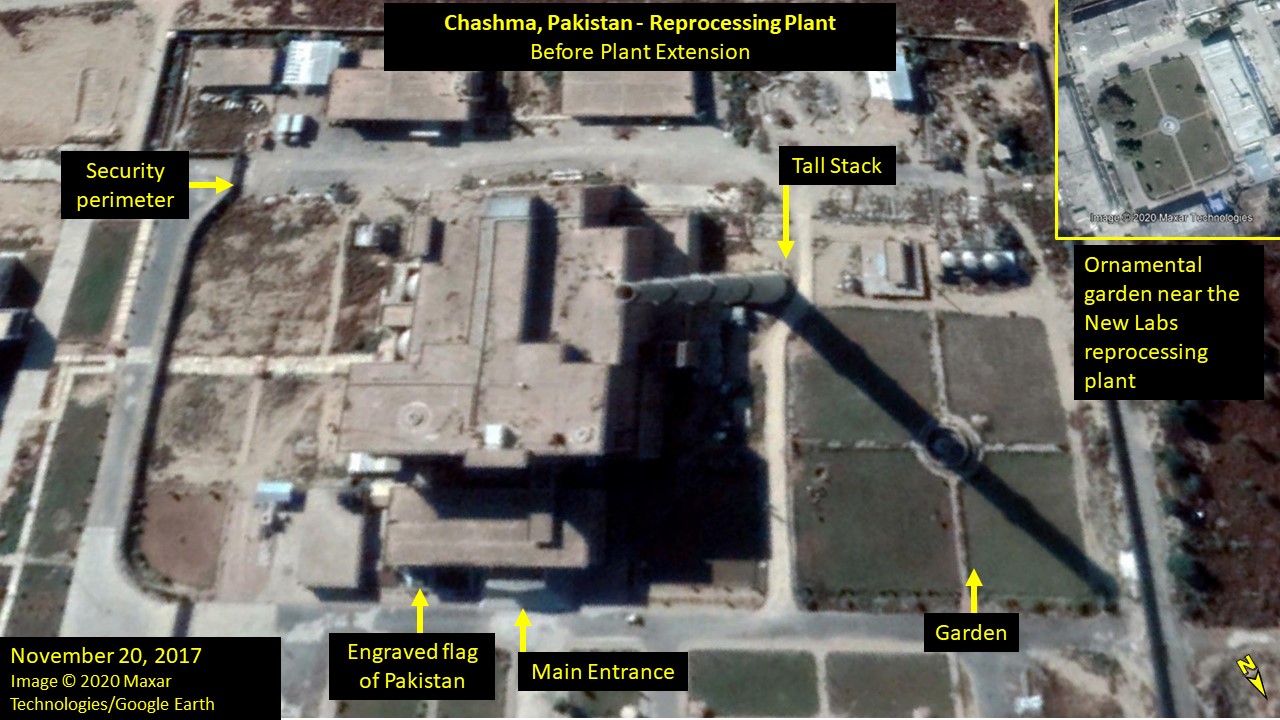
Figure 2. The Plutonium Separation Facility in 2017, before visible work on the extension began.
Recent Expansion of the Reprocessing Plant
Figure 3, a Google Earth image dated 9 May 2020 shows the presence of a new and previously undocumented extension of the facility near the tall stack.
Imagery shows that construction of the extension started at some point between April and September 2018. Figure 4, dated 19 September 2018, shows the ornamental garden and the paved road adjacent to the reprocessing facility have been removed, and foundations for the new extension, covering an area of approximately 30 x 30 m, have been laid in concrete, with development of exterior and interior walls. The area had been cleared and levelled beforehand, with large amounts of dirt removed and stockpiled across the street. It is evident by the steep slope on the north side, the ramp-like access to the foundation, the staggered levels of earth on the south side, and the amount of dirt piled outside of the construction area that at least part, if not the majority, of the building are designed to be underground.
The construction area has been enclosed by a new fence with two vehicle access points; a vehicle access point to the construction area has also been created in the perimeter security fence. Within the enclosed construction area, a canopy shelter, steel reinforcements, and building materials are visible. A possible connection or entrance to the main reprocessing building on the east face is apparent on magnification, which is more clearly visible in the subsequent Google Earth image dated 10 October 2018 (see inset to Figure 4). Figure 5, the full 10 October 2018 image of the facility, shows that construction had not progressed significantly.
Over a year later, Figure 6, dated 3 January 2020, shows the development of exterior walls to the extension, which are supported by buttresses. Steel reinforcement is observable within the interior of the extension which appears to define three large compartments.
In the following two months, construction of the extension progressed rapidly, as shown by Figure 7, dated 2 March 2020. The exterior walls of the building have been established, as well as an upper floor, which contains two sets of three cells separated by an access way running the length of the extension. The exterior walls, and interior compartment walls, are estimated to be 0.8 m thick and of apparent concrete construction, consistent with a purpose that requires shielding. A Google Earth image dated 9 May 2020 (see Figure 3 and Figure 8) shows further development of the above-ground portion of the extension building, which covers the compartments previously observed. Additional wall structures are visible, which could plausibly be mechanical and electrical plant rooms. On the north side of the extension appear to be three large access ports, which align with the three internal compartments identified in earlier imagery. Figure 9, the most recent Google Earth image, dated 13 September 2020, shows that the exterior and roof of the extension has been completed and the fencing around the construction area has been removed.
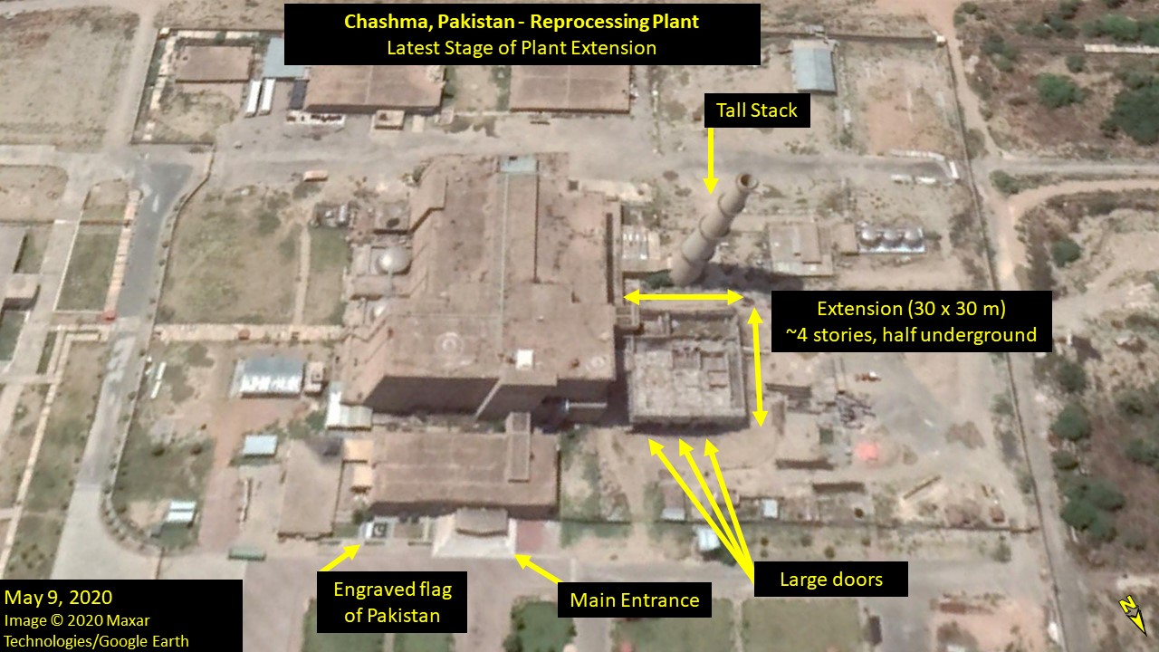
Figure 3. The extension to the Plutonium Separation Facility is near external completion in May 2020.
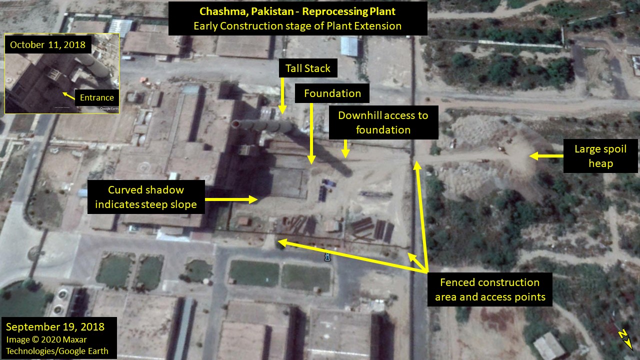
Figure 4. The construction of the extension to the Plutonium Separation Facility at an early stage in September 2018.
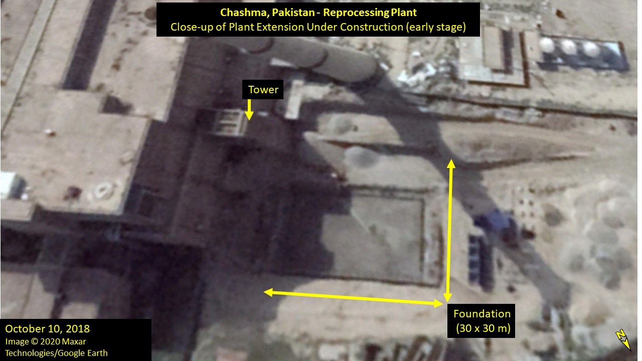
Figure 5. By October 2018, a 30 x 30 m foundation for the extension below ground level is visible in Google Earth imagery.
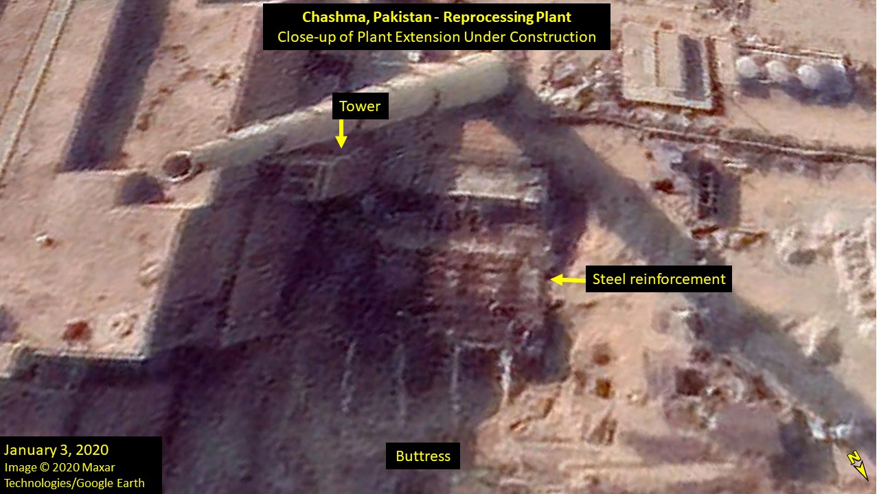
Figure 6. More than a year later, in January 2020, construction of the extension has progressed in height with steel reinforcement.
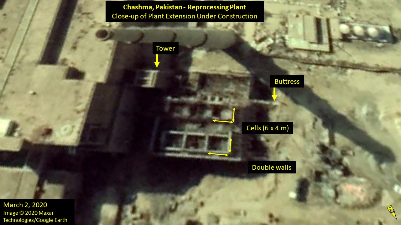
Figure 7. In this March 2020 Google Earth image the layout of one of the upper stories is visible: six cells with double concrete walls, and a hallway.
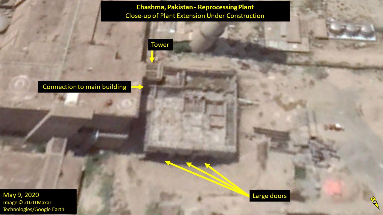
Figure 8. The extension is near external completion in May 2020, with a roof structure covering roughly half of the extension.
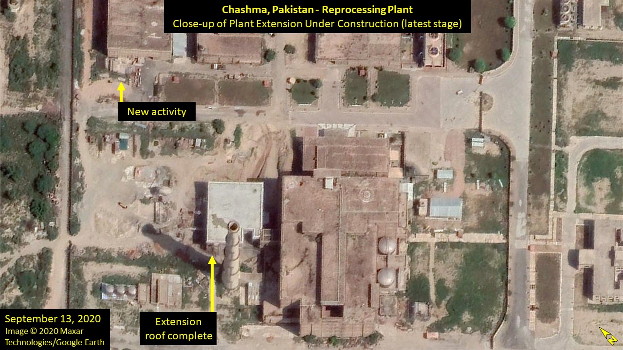
Figure 9. The extension is externally complete in September 2020.
The new extension has evidently been carefully designed and constructed to assimilate with the main reprocessing facility building, suggesting that it has an integral function. The interior compartments and moderately thick concrete walls suggest the purpose of the extension is to facilitate handling of high dose rate materials, such as spent nuclear fuels or radioactive wastes within shielded containers. The three large access points, and the fact that the extension appears to adjoin an existing access point to the main reprocessing facility building, suggest that the new extension could function to receive and unload irradiated fuel into the processing lines, and shear a different fuel type, such as LWR fuel, prior to chemically processing. Alternatively, or additionally, it could serve to export solid radioactive wastes, such as sheared fuel cladding. There are no other access points to the main reprocessing facility that could serve such a purpose visible in the available Google Earth satellite images.
Historical imagery shows three spur lines emerging from the main railway line which runs to the west of the reprocessing facility (see Figure 10.) In a 2002 image, the earliest available in Google Earth, the tracks and rails have been removed but their signature outline remains. As shown by Figure 10, one of the spur lines bears directly on the reprocessing facility and would have potentially terminated at the tall tower construction highlighted in Figures 5-8. This arrangement suggests that the design of the reprocessing facility intended to receive incoming fuel at the east face by rail transport, consistent with the siting and hypothetical purpose of the new extension building. The tower construction could plausibly house lifting gear or an elevator to move fuel skips from the reception area to the head end cave on an upper floor for shearing.
The original rail transport lines are thought to have been intended to transport fuel from the KANUPP reactor in Karachi – a distance of 900 km. The removal of the rail lines supports the conclusion that the Chashma reprocessing facility is instead separating plutonium from irradiated fuel from the Khushab reactors, located only approximately 80 km due east, or possibly in the future also from nearby Chashma reactors. There is no rail link between the two nuclear sites, which would require spent fuel from Khushab to be transported by road: the features of the extension building appear consistent with this mode of spent fuel reception.
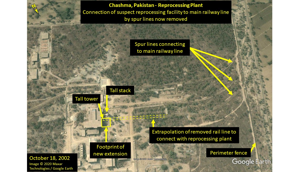
Figure 10. A 2002 image of the Plutonium Separation Facility indicates that spent fuel was originally to be transported by rail and received near the tall tower at the same building side as the new extension.
Analysis of other facilities co-located with the reprocessing plant
Figure 11 compares the reprocessing area in 2002 and 2020, highlighting co-located buildings which appear to be primarily of concrete construction and which may have a support function, given the external signatures and connection to the reprocessing plant via a network of trenches, identified by ISIS in 2015.16
Within the secure area is a building (labelled Building A, 58 x 45 m) which is co-located with a bank of five external cooling fans, to which it appears to be connected by a system of piping, as shown in Figure 11 and 12. This building is observed to have three small stacks mounted to the north face, which is at least one story greater in height than the main building. These signatures are consistent with the need to provide cooling for heat generating activities within the building, the reprocessing facility, or the adjacent structures. The small size of the building relative to the cooling fans seems more consistent with a support function. Alternatively, the building could possibly function as a fissile material store, for which recent modifications to the west face, including a new white roofed structure which could function as an access control point. The adjacent building (B, 82 x 32 m) has a double height section covering most of the footprint. The double height section and its aspect ratio, roof mounted stacks, and large entrance on the east face, are plausibly consistent with a spent fuel storage facility, which would need to accommodate a crane gantry for movement of fuel skips. However, neither of these two buildings (A and B) shows clear external signatures of additional security measures that might be expected if used for storage of fissile materials, such as a further security fence and access checkpoint.
Buildings A and B are present in the earliest available satellite image available on Google Earth, dated 19 October 2002, and the surrounding area appears overgrown, suggesting that they were part of the original phase of development. Indeed, the reprocessing facility and buildings A, B and D are all observable in the earliest available Landsat 5 Thematic Mapper (TM) imagery (30 m resolution) dated to 1988. Notably, no spur line approaching Building B is apparent in the 2002 Google Earth image, which, given the evident intention for spent nuclear fuel to be delivered by rail, may suggest its function as a spent fuel storage facility is less likely. Alternatively, the building could possibly function as a support laboratory.
Outside of the secure area are located a tall concrete building with an associated stack (C, 95 x 40 m) and a low building with what appears to be at least part concrete construction with a (damaged) panelled roof (D, 100 x 30 m). Figure 13 shows the two buildings in May 2020. Both buildings appear to be connected to the reprocessing facility by a concrete lined trench system largely covered by concrete shielding, consistent with transport of high-level waste (HLW). The situation of these buildings outside of the security fence which defines the reprocessing area, suggests that the function of these facilities is not associated with handling of fissile materials. Adjacent to the low building (D), a small building and three large cooling fans are visible, which were constructed during 2009-11. These signatures are consistent with the low building being a tank storage facility for liquid HLW, which requires active cooling to remove decay heat. Also of interest are two approximately one kilometre long trenches connecting this facility with two possible disposal wells beyond the outer perimeter fence, visible in October 18, 2002, imagery shown in Figure 14. These trenches are difficult to identify in more recent imagery, due to overgrowth and the shorter trench being obscured by new development. These trenches may signify an original intention to dispose of some higher activity liquid wastes by borehole injection to the subsurface, as was previously practiced in Russia, for example.
Construction of the tall concrete building (C) and stack was reported by ISIS in 2015, using commercial satellite imagery, at which time the exterior of the building was complete.17 Using historic imagery available in Google Earth, the construction of this facility can be analysed in new and revealing detail, as shown in Figure 15. The first available image showing construction of this facility is dated November 19, 2009; it shows the foundation for the building which is evidently constructed in two wings, each symmetrical about a central spine. The foundations appear to be set at basement level, as shown by the downward slope to the excavation area and shadow profile. The earliest image showing the facility to be externally complete is dated November 26, 2013. The front (west facing) wing of the building is shown in later imagery to have windows and small internal structures, which suggest the presence of shielded compartments at basement level (possibly for radioactive wastes). The rear wing contains at least one very heavily shielded section with external (0.8 m thick) and internal (1.3 m thick) walls, which may be utilised to the full height of the building. This section, uniquely, contains a roof vent, which interfaces with a roof mounted service building with two inlets or outlets; a small additional vent may also be present. This section appears to be connected to the neighbouring annex by underground pipes and an additional pipe to the roof mounted service building. The annex itself has two small stacks mounted on the west wall and exterior pipework is visible on the north wall which may connect to the four fans. Within the large rear wing, internal cells are visible within one of the larger forward sections, which could function as hot cells. Taken together, the external and internal signatures of the rear wing of the building are plausibly consistent with those of a high level waste vitrification facility, which would require: heavy shielding for operational activities; cooling for stored vitrified waste containers; a stack for release of volatile radionuclides (e.g. iodine, ruthenium) and gas emissions; and a buffer store of liquid HLW (located in the adjacent building with co-located cooling fans). The front wing of the building could plausibly accommodate process engineers, managers and support laboratories. Open source information documents a project by PAEC to procure vitrification technology for the immobilisation of high level radioactive wastes arising from nuclear fuel reprocessing, which was in progress during 2007. This information is consistent with Google Earth satellite imagery dated 17 August 2007, which appears to show ground clearance in preparation for construction of the possible vitrification facility, the foundations of which are present in the subsequent imagery dated November 19, 2009.
The scale of this facility deserves comment. If the footprint of the rear wing (40 x 67 m, or 2,680 m2) is assumed to include the vitrification plant itself and storage facility for vitrified HLW canisters (plausibly, the heavily shielded, ventilated, rear section), then it is comparable with the Tokai Vitrification Facility (TVF), Japan, for which these functions are accommodated in a plant occupying a footprint of 2,600m2 (in a five storey building, including two basement levels).18 The TVF plant entered operation in 1992, to immobilise HLW from the Tokai Reprocessing Plant. The design capacity of the Tokai Reprocessing Plant was 90 tHM / year (for LWR fuel), similar to the estimated 100 thM capacity of the Chashma plant (for PHWR fuel). Thus, the footprint of the possible vitrification facility is plausibly consistent with that required to support sustained operation of the Chashma reprocessing plant.
There is no open source information persuasive of indigenous development of HLW vitrification technology in Pakistan. The sheer scale of the possible HLW vitrification plant at Chashma would therefore imply a hitherto unknown research and development programme, and facilities, associated with the pilot scale New Labs reprocessing facility at PINSTECH, or the contribution of expert foreign support. Furthermore, the expansion of the waste management area facilities demonstrates preparation for treatment and storage of a substantial waste inventory arising from the reprocessing facility.
Some internal and external signatures of the possible HLW vitrification facility are also consistent with a second reprocessing plant, spent fuel storage, or intermediate level waste treatment plant. However, the absence of a security fence and features associated with a fuel receipt capability, with respect to a reprocessing and fuel storage function, and the presence of the emissions stack with regard to the spent fuel storage and intermediate level waste treatment function, mean these are less plausible hypotheses.
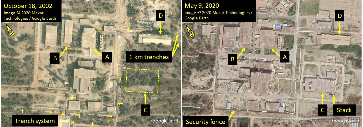
Figure 11. A comparison of the buildings associated with the Plutonium Separation Facility in 2002 and 2020. Three of the four key buildings appear to have been part of the original design of the site; the fourth was added to the site in 2007-2009.
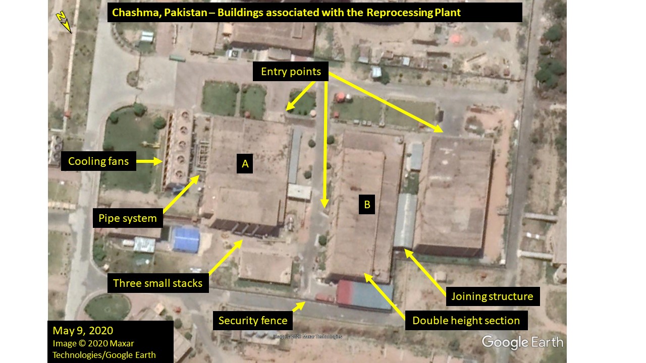
Figure 12. Visible key features of two of the original buildings associated with the Plutonium Separation Facility.
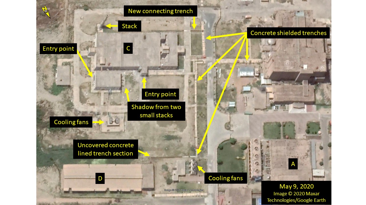
Figure 13. The buildings of interest are connected to one another and the Plutonium Separation Facility by a network of trenches, some of which are concrete-shielded.
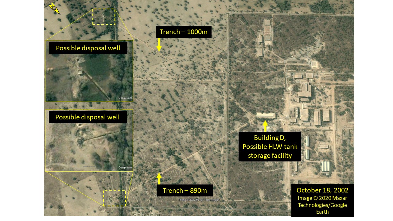
Figure 14. One of original buildings of interest (here shown in 2002) shows features consistent with a HLW tank storage facility.
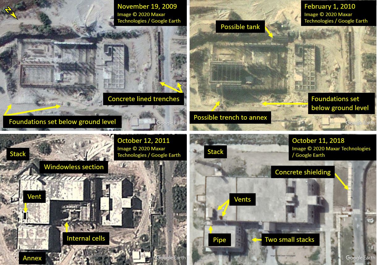
Figure 15. One of the buildings of interest was added to the site more recently; construction was first visible in Google Earth in 2009 imagery and external construction was largely complete by 2011. This figure shows the building from 2009 to 2018 (top left, top right, bottom left, bottom right).
Development of possible waste management area
ISIS previously identified a possible waste management area, connected to the reprocessing plant in 2007,19 which has developed considerably over the last decade, as shown in Figure 16. In this area, some buildings of concrete construction, possibly lightly shielded waste treatment facilities, are linked to the reprocessing plant by a trench network. These trenches are not concrete lined and are filled in with earth, rather than covered by concrete shielding, suggesting the transport of low or intermediate level liquid wastes. The waste management area has been progressively developed over the last decade at least, with refurbishment and possibly re-roofing of original surface disposal cells in 2011, construction of new storage facilities between 2013-2020, and development of new access roads.
Open source information reports the development of a regional interim waste storage facility at the CHASNUPP 1 (C-1) site,20 which refers to the location of the safeguarded PWR reactor. The facility, reported to be under construction in 2014, includes over-packing and storage facilities. The over-packing building (22 x 22 x 5m) is dedicated to cement over-packing of mild steel waste drums of solid / solidified wastes, in reinforced concrete containers, with concrete capping. The storage building (65 x 22 x 5 m) is stated to accommodate 1,000 reinforced concrete containers, stacked thee high. These buildings were located on the CHASNUPP 1 site, as shown in Figure 16, and construction is verified to have been in progress in November 2013, using historical Google Earth imagery. The dimensions of these facilities match that of four new buildings on the waste management site, developed between 2013-2020, and one original building, suggesting these may have an identical function. Also visible in the most recent image of the waste management area are characteristic yellow coloured mild steel waste drums, present on the concrete apron of the surface storage and disposal facilities, which are documented to be used for cement encapsulated solid waste and disposed in near surface trenches at PINSTECH.21 Therefore, the other buildings of concrete construction in the waste management area are likely to be cement encapsulation facilities, which would be required to manage the stripped fuel cladding and other wastes from the reprocessing facility in line with international practice.
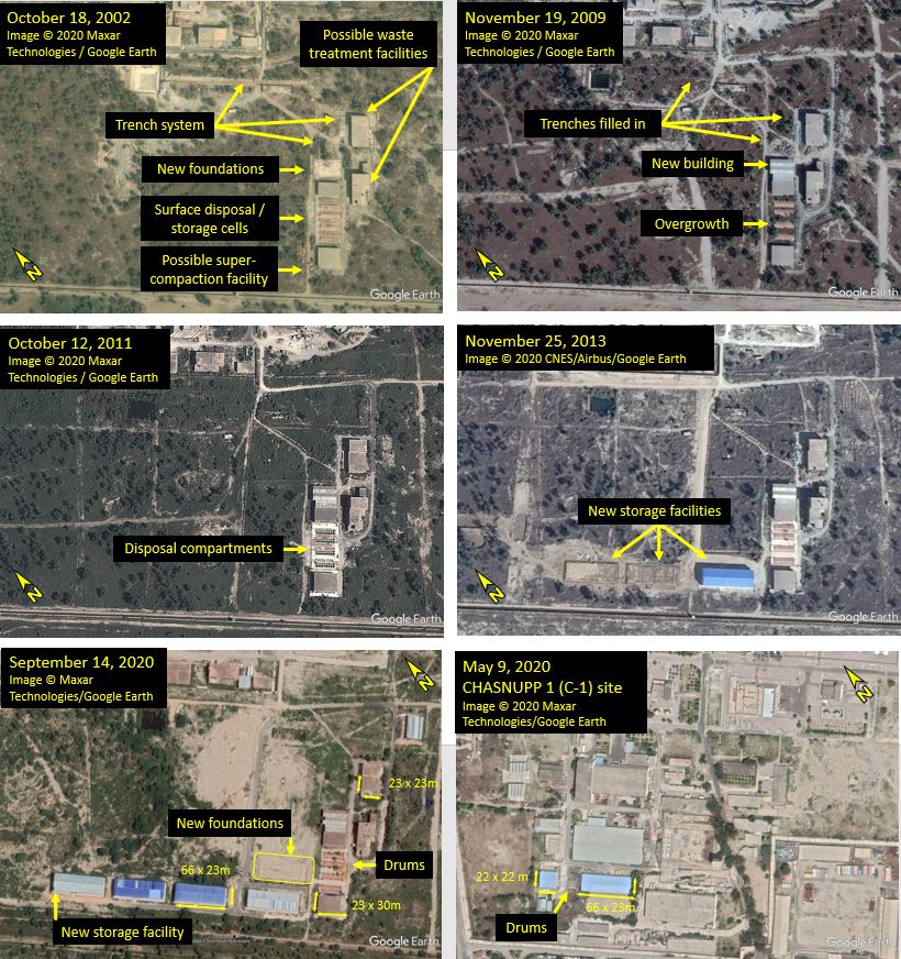
Figure 16. A possible waste management area, connected to the reprocessing facility, has developed considerably over the last decade. This figure shows the possible waste management area over time from 2002 to 2020 (top left, top right, middle left, middle right, and bottom left) and identified new storage facilities which appear externally identical to a storage facility as CHASNUPP-1 (bottom right).
Conclusion
Analysis of recent and historic public domain satellite imagery has identified a significant and previously undocumented extension to the Chashma reprocessing plant and considerable development of co-located infrastructure over the last decade. The siting and both internal and external signatures of the new extension building suggest that its function may be an increased capacity to receive spent nuclear fuel for reprocessing transported by road. If this is indeed the function of the extension, then it can be reasonably interpreted to signal an intention to scale up fuel throughput and reprocessing (which may have already commenced, at least in a commissioning capacity). At a minimum, the extension to the plutonium separation plant and associated facilities at Chashma demonstrates an on-going commitment to invest in and operate plutonium separation technology at industrial scale. It is not clear from satellite imagery whether the Chashma reprocessing plant has continued to operate during the construction. If not, the pace and scale of recent infrastructure developments signal that resumption of reprocessing activity may be expected in the near future.
This is supported by the wider development of the site infrastructure. A review of historic imagery has recognised external and internal signatures of previously identified buildings as consistent with those expected of a HLW tank storage facility and HLW vitrification facility.
1. Neil Hyatt is Professor of Nuclear Materials Chemistry at the University of Sheffield. ↩
2. David Albright and Paul Brennan, “Chashma Nuclear Site in Pakistan with Possible Reprocessing Plant,” Institute for Science and International Security, January 18, 2007, https://isis-online.org/uploads/isis-reports/documents/chashma.pdf ↩
3. David Albright and Serena Kelleher-Vergantini, “Pakistan’s Chashma Plutonium Separation Plant: Possibly Operational,” Institute for Science and International Security, February 10, 2015, https://isis-online.org/isis-reports/detail/pakistans-chashma-plutonium-separation-plant-possibly-operational/12 ↩
4. Feroz Hassan Khan, Eating Grass: The Making of the Pakistani Bomb, (Stanford: Stanford Security Studies, 2012). ↩
5. “Pakistan’s Chashma Plutonium Separation Plant: Possibly Operational.” ↩
6. “Chashma Nuclear Site in Pakistan with Possible Reprocessing Plant.” ↩
7. David Albright and Paul Brennan, “Pakistan Expanding Plutonium Separation Facility Near Rawalpindi,” Institute for Science and International Security, May 19, 2009, https://isis-online.org/uploads/isis-reports/documents/PakistanExpandingNewLabs_19May2009.pdf ↩
8. See Sarah Burkhard, Allison Lach, and Frank Pabian, “Khushab Update,” Institute for Science and International Security, September 7, 2017, https://isis-online.org/isis-reports/detail/khushab-update/12 https://isis-online.org/isis-reports/detail/khushab-update/12 ; and David Albright, and Serena Kelleher-Vergantini, “Khushab Reactors Operational While New Construction Progresses,” February 29, 2016, https://isis-online.org/uploads/isis-reports/documents/Three_Khushab_Reactors_Operational_February_29_2016.pdf ↩
9. “Pakistan’s Chashma Plutonium Separation Plant: Possibly Operational.” ↩
10. Q. Mehboob, “Spent Nuclear Fuel Management and Cost Estimation Methodology (Pakistan),” PowerPoint Presentation at “IAEA Technical Meeting on Cost Estimation Methodologies for Spent Fuel Management,” Vienna, November 5-8, 2019. ↩
11. Z. Shah, “Current Status of Radioactive Waste Management in Pakistan,” PowerPoint Presentation at “PAEC-IAEA National Workshop on Strategy and Methodologies for the Development of Near Surface Disposal Facilities,” NCP Islamabad, February 24-28, 2014. > ↩
12. See “Chashma Nuclear Site in Pakistan with Possible Reprocessing Plant” and “Pakistan’s Chashma Plutonium Separation Plant: Possibly Operational.” ↩
13. “Pakistan’s Chashma Plutonium Separation Plant: Possibly Operational.” ↩
14. Eating Grass: The Making of the Pakistani Bomb. ↩
15. See “Chashma Nuclear Site in Pakistan with Possible Reprocessing Plant” and “Pakistan’s Chashma Plutonium Separation Plant: Possibly Operational.” ↩
16. “Pakistan’s Chashma Plutonium Separation Plant: Possibly Operational.” ↩
17. “Pakistan’s Chashma Plutonium Separation Plant: Possibly Operational.” ↩
18. T. Tsuboya and N. Tsunoda, “The Japanese Vitrification Program,” Waste Management Symposium, 1988, 181-188. ↩
19. “Chashma Nuclear Site in Pakistan with Possible Reprocessing Plant.” ↩
20. “Current Status of Radioactive Waste Management in Pakistan.”↩
21. Eating Grass: The Making of the Pakistani Bomb. ↩
 email us
 twitter