New Information about Iran’s Production of Uranium Hexafluoride under the Amad Plan
The Iran Nuclear Archive contains new information about Iran’s secret efforts in the early 2000s to make uranium hexafluoride (UF6) for its nuclear weapons program, codenamed the “Amad Plan.” Figure 1 shows a simplified schematic representing the Amad Plan’s pathway to build five nuclear weapons and an underground nuclear test site, focusing on its main tasks, with uranium hexafluoride production highlighted.
“Project 5” of the Amad Plan had responsibility for ensuring the supply of UF6, the essential feedstock for the military Al Ghadir enrichment plant, a plant slated to make weapon-grade uranium for use in nuclear weapons, known today as the Fordow Enrichment Plant. In general, Project 5 was in charge of uranium mining, milling, and conversion for the nuclear weapons program, operating in parallel, albeit connected partially and indirectly, with the much larger, more open Atomic Energy Organization of Iran’s (AEOI’s) uranium mining and conversion efforts, those activities largely concentrated at the Saghand uranium mine, the Ardakan uranium mill, and the Esfahan uranium conversion facilities.
Other Institute studies have explored Project 5’s Gchine uranium mine and mill project and its post-Amad coverup, featuring the role of the military contractor Kimia Maadan.2 The International Atomic Energy Agency (IAEA) has discussed the military program to produce uranium tetrafluoride (“green salt”), an intermediate compound vital to produce uranium metal and uranium hexafluoride, its inspectors identifying the central role of Project 5 and the contractor Kimia Maadan in that production.3 The IAEA had obtained a process flow diagram for a bench-scale, one metric tonne per year operation, and preliminary design plan for a 50 metric tonnes per year production facility.4 Despite technical inconsistencies in one of the diagrams, the IAEA judged the drawings as credible and separate from the green salt process at the AEOI’s Esfahan green salt production facilities, associated principally with making uranium hexafluoride for the Natanz uranium enrichment plant. 5
Prior to Israel’s seizure of the Iran Nuclear Archive, the IAEA, and Western governments knew little about the Iranian nuclear weapons program’s efforts to obtain or make uranium hexafluoride. According to the information in the Nuclear Archive, these efforts were slated for secret nuclear facilities outside the required inspections by the IAEA, in violation of the overarching Nuclear Non-Proliferation Treaty. The focus of this report is a subset of this information in the Nuclear Archive from May 2003 on a planned facility, designed by the Project 5 contractor Kimia Maadan Group, and assessed to make significant amounts of uranium hexafluoride and fluorine gas, one of its key precursors. It appears to be a scaled-up version of a smaller, pilot plant, likely one independent of the AEOI and already operational at that time.
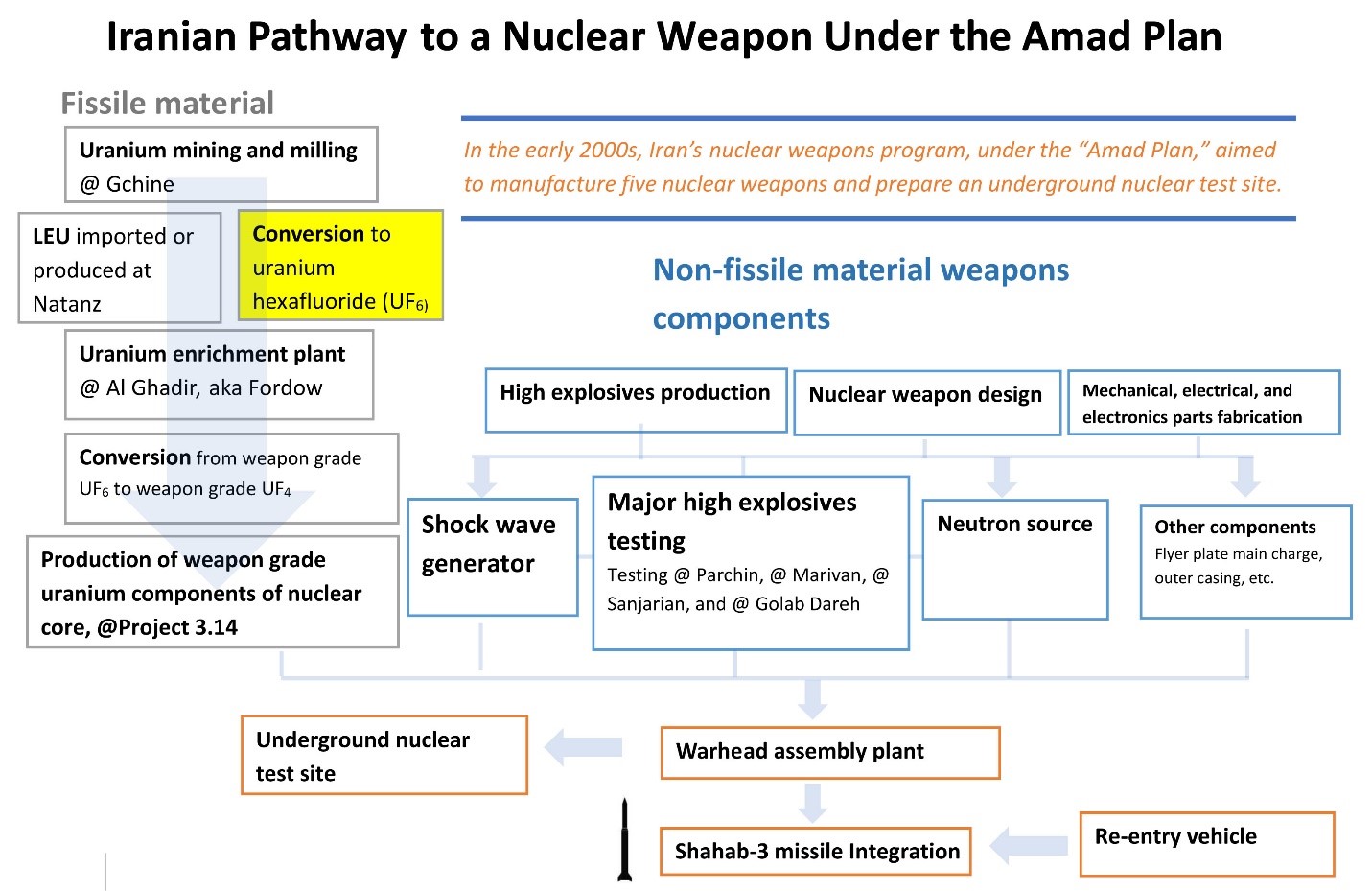
Figure 1. Iranian Pathway to a Nuclear Weapon Under the Amad Plan. This chart generally flows from the top to the bottom, ending with a nuclear warhead on a Shahab-3 missile. Some activities occur simultaneously and are therefore presented on the same level. A more complete, interactive pathway chart can be found at https://isis-online.org/isis-reports/detail/iranian-pathway1-to-a-nuclear-weapon-under-the-amad-planwhat-we-learned-fro/8
New Information
The new information from the archive includes a letter and three design drawings:
- The letter, dated May 24, 2003, discusses the design of a plant that handles uranium hexafluoride, sent from Group 7, Amad’s Health and Safety Group, to the project manager concerning a new, temporary Tehran site. In this Institute report, the site is called the New Tehran Site, as explained below. The letter does not indicate its location and does not explain why it is called temporary (see below).
- Three plant designs contain detail of this new facility, marked as designed by Kimia Maadan Group, assessed by the Institute as being related to making pure fluorine gas (F2) and likely uranium hexafluoride.
According to senior Israeli intelligence officials with deep knowledge of the archive, the site was not built. Moreover, they could not determine its intended annual capacity, although they assessed it was being designed to make significant amounts of uranium hexafluoride. Despite being labelled the new Tehran Plant in the letter, they assessed the site would have been built outside Tehran.
One development possibly contributing to delays in completing this plant could have been technical problems in producing uranium hexafluoride. Another factor could have been a senior level Iranian decision to use low enriched uranium hexafluoride produced in the AEOI’s Natanz enrichment plant as the feedstock for the secret Al Ghadir enrichment plant, greatly accelerating weapon-grade uranium production, compared to starting with natural uranium. 6 With the use of enriched uranium, the annual output of weapon-grade uranium at Al Ghadir would increase threefold, eliminating the need for an independent production capability to make natural uranium hexafluoride.
The Health and Safety Letter from the Amad Plan’s Group 7
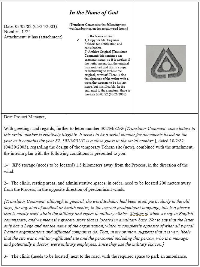
The May 24, 2003 letter, with the logo of Group, or Directive, 7, from the Health and Safety Manager to an unnamed “project manager,” with a copy to Mr. Engineer Rahbari for “notification and consultation,” lays out conditions on the storage and use of “XF6” and “HF” in the design of the “temporary Tehran site (new).” “X” likely stands for “U” as in uranium; other documents similarly try to obscure the subject being uranium. HF is the chemical symbol for hydrogen fluoride, or when dissolved in water, hydrofluoric acid. These fluorine-containing compounds are dangerous to work with and require extensive safety measures, explaining Group 7’s involvement.
The letter lays out a set of recommendations and conditions (quoting from the letter):
1- XF6 storage (needs to be located) 1.5 kilometers away from the Process, in the direction of the wind.
2- The clinic, resting areas, and administrative spaces, in order, need to be located 200 meters away from the Process, in the opposite direction of predominant winds.
3- The clinic (needs to be located) next to the road, with the required space to park an ambulance.
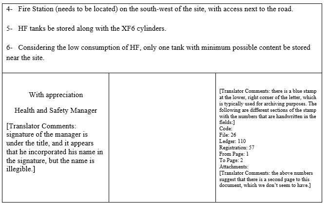
4- Fire Station (needs to be located) on the south-west of the site, with access next to the road.
5- HF tanks be stored along with the XF6 cylinders.
6- Considering the low consumption of HF, only one tank with minimum possible content be stored near the site.
The letter in Farsi and its English translation are in Figures 2 and 3.
The conditions of the Health and Safety group to physically separate the main plant from the clinic and the storage sites would in the event of an accident reduce the magnitude of the accident and limit toxic effects of uranium hexafluoride and hydrogen fluoride on the site’s workers and the environment while ensuring that plant managers could institute and control emergency procedures. When UF6 is exposed to air, through a breach of a storage container, for example, it reacts to form a deadly cloud of HF and uranium fluoride compounds–the former can sear the lungs of anyone who inhales it; the latter can cause kidney damage.
The letter does not explain the reason for a UF6 storage location at a distance of 1.5 kilometers from the main facility, perhaps reflecting Group 7’s conservatism in dealing with a new, dangerous industrial process. The same type of conservativism was seen in Group 7’s review of operations at the Taleghan 1 high explosive chamber at Parchin, insisting on very strict uranium limits, before certifying the chamber for routine operation. 7 It may also suggest usage of relatively large UF6 containers. The distance is consistent with the one-mile evacuation radius for the rapture of a heated 14-ton UF6 cylinder set by the U.S. Nuclear Regulatory Commission in 1988, based on resulting HF and uranium releases. According to the report, “For less than 50 kg of UF6 at risk a distance of 100 meters would be appropriate. For 500 kg of UF6 at risk a distance of 500 meters would be appropriate, and for a 14-ton cylinder, one mile would be an appropriate distance.”8 One mile is approximately 1.6 kilometers. The possible use of U.S. nuclear safety standards would not be surprising. Group 7 used U.S. Environmental Protection Agency standards in making its certification about the Taleghan 1 chamber.
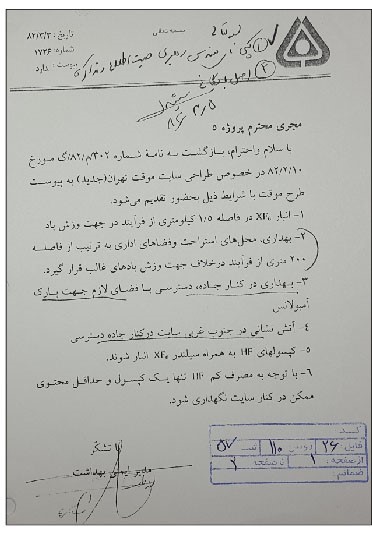
Figure 2. A letter from the Nuclear Archive, in Farsi (translation in Figure 3), explaining an interim plan to safely handle uranium hexafluoride and hydrogen fluoride, both toxic compounds in the New Tehran Site. The logo is that of Group 7, of the Amad Plan, namely its Safety and Health group. A similar logo is seen on a letter from the Manager of the Manager of Health and Safety to the head of Project 3030, which reviewed and certified the safety of the experiments in the Taleghan 1 chamber involving uranium.
Figure 3. Translation of Farsi letter from Group 7 to the project manager about the New Tehran Site.
Plant Design Drawings
The three design drawings show an industrial building, its shape like a “Y,” with links to the Group 7 letter above, all consistent with a plant to produce fluorine gas and uranium hexafluoride. Figures 4, 5, and 6 show these drawings, with English translations of their Farsi annotations, all located at the end of the report. It should be noted that many of the annotations on the drawings are in English, specifically in the section assessed to be for fluorine production.
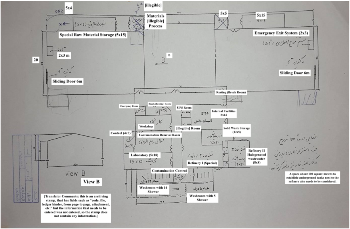
The first schematic, called design 1 in this report, is an early, undated building design (see Figure 4). It apparently shows a one story, standard looking industrial building. The schematic does not have a key or other identifying mark.
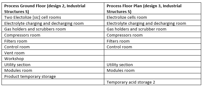
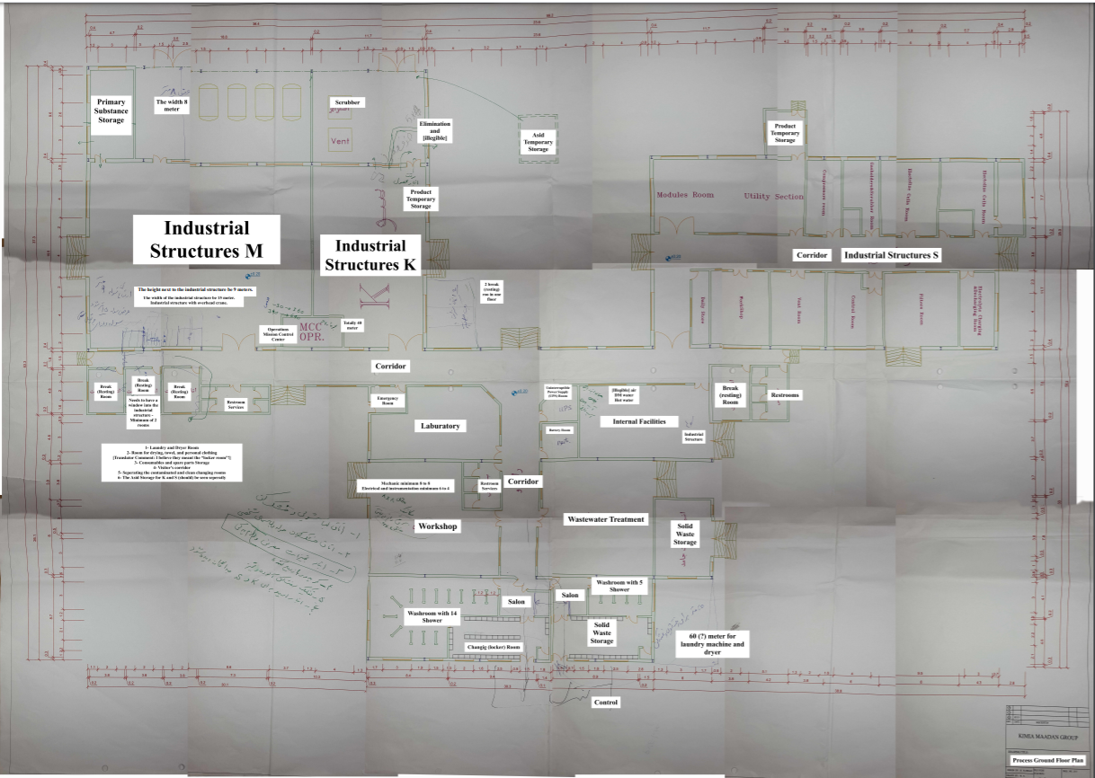
The second design drawing, called design 2 and shown in Figure 5, is titled “Process Ground Floor Plan” in its key. It has far more details than design 1, identifies B. Rahbari as the designer and “M.A.” as the drawer of the design, lists a drawing date of May 24, 2003, and labels Kimia Maadan Group prominently in the key. The design is given the file code (CAD ref): C-0-C10 and Proj. 5/15, translated in American English as 5.15.
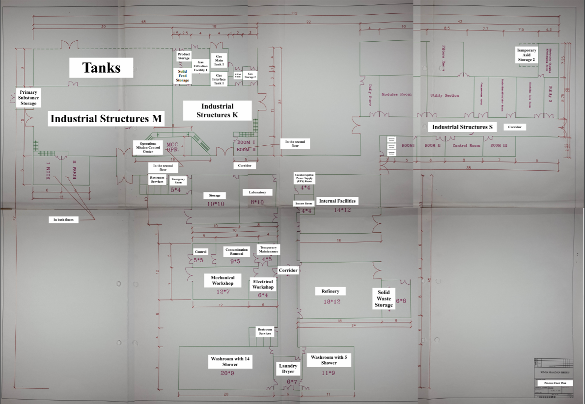
The third design, called design 3 and shown in Figure 6, is similar to the second one, but titled “Process Floor Plan.” It has the same date, designer, project code, and drawer as the second design. It also features Kimia Maadan Group on the key. The file code is different, C-0-C18, as are many of the annotations on the drawing.
The prominent presence of Kimia Maadan Group on two of the drawings implies that Kimia Maadan was involved at least in the design of the plant. It may have also assisted the procurements for the site.
Rahbari, mentioned in the key on designs 2 and 3, is likely the same Rahbari as in the letter from Group 7 to the project manager, copied in the letter to notify him of the additional changes that need to be made to the design. IAEA data include an A. Rahbari, who could be the same person as above. The IAEA has information associating him with procuring Siemens programmable logic controllers (PLCs) for industrial plants, linking him to the Amad Plan’s Gchine mill. In light of the new archive information, this view needs reexamination as to whether he was also involved in procuring for the New Tehran Site.
Designs 1 and 2 have several handwritten annotations in Farsi. These appear to suggest changes or amplifications to specific parts of the drawings.
The key in designs 2 and 3 list Project 5.15, typically associated with the Gchine project. Its meaning on this drawing is unclear, based on available information.
The three designs could be different versions, with one more advanced in its planning than the previous one, suggested for example by their file code numbering differing, e.g. C10 vs C18. Additionally, handwritten notes on C10 appear to have been integrated into C18. For example, a handwritten note on C10 says “Laundry and Dryer Room,” and C18 has an integrated Laundry and Dryer room, whereas there was none in C10.
Annotations imply that certain rooms extend into the second floor, but it is doubtful that the entire building consists of two stories. No elevator could be identified, and symbols in design 2 that could represent stairs appear to lead outside. Additionally, an overlay of the two designs shows that it is unlikely that the two designs represent two stories of the same building; while the width-to-length ratio of the overall area is the same, the three wings in the two designs have different dimensions and do not appear to overlay well enough to represent two stories of one building. Lastly, many of the redundancies in the two floors would be difficult to explain.
The facility is roughly shaped as a “Y,” with three apparent sections. Two wings appear related to production and processing and the third is involved in support activities, in particular decontamination, waste processing and waste storage. The overall dimensions of the footprint of the entire building as drawn in design 3 is 112 by 72 meters.
Industrial Structures S
One wing, labelled “Industrial Structures S,” appears to be devoted to making fluorine gas (F2) via electrolysis. It includes designated space for electrolyte charging, electrolysis cells, a scrubber, presumably to remove HF from the product, and a compressor room to compress the gas before its transfer to the temporary product storage.
These annotations are consistent with a process to make F2 using hydrogen fluoride in the form of anhydrous hydrogen fluoride (AHF), a pure form of HF with minimal traces of water. AHF and a fluoride-containing salt are combined in electrolytic cells to produce F2. HF is regained in the process, which is consistent with the letter’s mentioning of “low consumption of HF.” This section has a control room (Design 2 shows it with a double door). Design 1 lists an emergency exit at the end of this wing. The English labels on the various rooms in designs 2 and 3 are reprinted below:
Industrial Structures K and M
The remaining industrial parts of the plant design are labelled less clearly, with an apparent conscious attempt to obfuscate the plant’s purpose. However, there are several indications that fluorine is not the final, or at least not the only product of the plant, and the lay out remains consistent with uranium hexafluoride production, a process where F2, in unreactive nitrogen gas, is reacted with uranium tetrafluoride (UF4) in a special reactor. Afterwards, the UF6 gas is purified and then passed through a condensing system, where it is cooled, and drained into transport tanks.
This wing, comprising about a third of the plant’s floor space, features two main rooms, “Industrial Structures M,” and “Industrial Structures K,” both featuring specific instructions, with a shared second-floor “Operations Mission Control Center” (see design 3). The larger area of the two, structure M, is described as 9 meters high and 15 meters wide, holding an overhead crane. Two adjacent rooms are labeled to be on the second floor, specified to have a window providing view of structure M.
The following observations of Structures K and M support this wing being for the fluorination of uranium tetrafluoride into UF6, where the reactor would likely be located in one structure, while purification, and subsequent condensation into storage tanks would occur in the other.
1) Design 1 labels a room adjacent to structures M “special raw material storage,” and a “Refinery I, Special,” obscure terms for a technical drawing, implying that something sensitive is produced there. Moreover, design 1 labels another room in another wing clearly as “Refinery II, halogenated wastewater.” Fluorine-containing waste would be classified as halogenated.
2) Industrial structure S features a temporary product storage, implying that there is a product, yet only temporarily. The storage room is small compared to storage areas in structures M and K. The largest storage in structure M is labeled “Tanks” in design 3 and has four tanks drawn in it in design 2, with a width specified as 8 meters. Of note, the letter from the health and safety group makes no note of safe storage of fluorine gas, which is very toxic. This could imply that storage requirements are already satisfactory, or that there are no large amounts of fluorine stored for a long time, since it is used up in the next step to UF6.
3) The wings are connected by long corridors, but distant from another, resulting in the Y shape. This could imply that the processes in each wing are related, while the effect of a potential accident in one wing on the remaining two is minimized.
4) The designs do not specify a fluorination reactor, but a video and a series of photos of the AEOI’s Uranium Conversion Facility (UCF) at Esfahan support that fluorination occurs in rooms with high ceilings and a crane.9 An industrial fluidized bed reactor, a common reactor type for direct fluorination of UF4 and the type of reactor used in the UCF, typically requires a relatively tall structure.10 The video of the UCF avoids showing much of the UF6 production process, let alone a reactor, nonetheless it shows a high ceiling and an overhead crane used for lifting and lowering UF4 and UF6 containers. It also shows a large structure, which appears to be separate from the reactor room, hosting probable compressors and condensation equipment.
5) The architecture of the industrial structures M and K could have resembled the UCF at Esfahan in other aspects. An image of the UCF by Behrouz Mehri, AFP, licensing required and distributed via Getty images, taken on August 9, 2005, shows processing equipment requiring a tall room structure and a small set of stairs, similar to what is described in handwritten notes for structure M on design 2. Another image, dated February 3, 2007, also by Behrouz Mehri, AFP, licensing required and distributed via Getty images, shows a second-story window in the UCF with a view into the processing hall, possibly a break room, judging by the appearance of the room and the picture hanging on the wall. Similarly, handwritten notes in design 2 state “break (resting) room needs to have a window into industrial structure,” where design 3 notes that the room should be “in both floors.” A symbol made of short parallel lines found near all rooms labelled to be in the second floor or in both floors could represent sets of stairs.
6) At the end of the UF6 production process, fumes are scrubbed from uranium fluorides and HF and released through a vent. Structure K features a scrubber, a vent, a temporary acid storage, and a temporary product storage.
7) Also adjacent to structure K is an area with separate rooms for solid feed storage, product storage, gas filtration facility 1, gas main tank 1, gas interface tank 1, and gas storage 1, where solid feed is consistent with UF4, which is a green solid at room temperature and pressure.
8) All three designs feature a relatively large area for tanks next to industrial structure M. The letter’s first point is that XF6 needs to be stored more than a kilometer away from the “process,” this perhaps meaning instead of keeping it in on-site storage. Other expected health and safety measures not listed in the letter appear to already be in place, including many exits (over 20 doors leading outside), washrooms with showers and at least one fume scrubber with vent.
Third Wing
The third wing appears to be a support area. It contains a laboratory, workshop, and an uninterruptable power supply (UPS). This wing is also for de-contamination and waste processing and storage. It has many showers and areas separated into contaminated and clean changing rooms. It has rooms to decontaminate workers, called “contamination control,” and “contamination removal room.” One area has 14 showers next to a changing or locker room. Another washroom with five showers is next to a solid waste storage room.
This area of the plant also has wastewater treatment and another solid waste storage area. Design 1 shows a refinery processing halogenated wastewater, waste defined as containing any chemical with fluorine, chlorine, bromine, iodine, or, less commonly, astatine or tennessine.
A handwritten comment on design 1 identifies a space of about 100 square meters next to the facility for holding underground tanks. Their purpose is not stated, but they could be to contain waste from the plant’s operation.
Taking Stock
At the very least, this new information from the archive suggests the Amad Plan’s intention to build in the spring of 2003 a sensitive plant handling both uranium hexafluoride and hydrogen fluoride. The reference to UF6 storage indicates that UF6 was either the precursor or the product of the process at the plant.
Assessments of both the design drawings and letter support that Industrial Structure S would have made fluorine gas, a compound often produced with the intention to use it in a nearby industrial application. The likely production of F2 would eliminate several other uranium conversion steps in which HF is typically one of the main reactants, in particular the conversion from UO2 to UF4. It also reduces the likelihood of conversion of weapons grade UF6 to weapons grade UF4, where F2 may be used, but not at a scale that would require on-site industrial production.
Non-nuclear uses or civilian nuclear uses of the fluorine gas under the AEOI are unlikely for several reasons. First, Group 7, the Health and Safety Group of the Amad Plan, was consulted. Second, Group 5 of the Amad Plan, and Kimia Maadan, a military contractor of the Amad Plan, were involved in designing the plant. Third, the plant design was surrounded by secrecy; the deliberate use of an “X” in XF6 in the letter, the obscure “special” materials labelling in the designs. As a result, the most likely industrial application of the fluorine, carried out in Industrial Structures K and M of the plant, is the fluorination of UF4 to produce uranium hexafluoride for the Amad Plan.
Apparently, the IAEA and Western governments did not know about this facility prior to the seizure of the Nuclear Archive. The site’s secrecy and documented involvement of Groups 5 and 7 of the Amad Plan suggest that Iran was not intending to declare this site to the IAEA, unless discovered, such as was the case with the Natanz enrichment plant and the Gchine uranium mine.
Figure 4. Schematic 1 from the Nuclear Archive, undated, assessed to be an earlier design of the new Tehran plant than represented in the ones in Figures 5 and 6. Translation from the Farsi original by the Institute.
Figure 5. Schematic 2 from the Nuclear Archive, dated May 24, 2003, assessed to be a more advanced design of the new Tehran plant, containing handwritten notes of changes that are still to be made. Translation from the Farsi original by the Institute.
Figure 6. Schematic 3 from the Nuclear Archive, dated also May 24, 2003, but assessed to be more finalized than schematic 2. Translation from the Farsi original by the Institute.
[1] We thank Mark Gorwitz and Olli Heinonen for their helpful comments.
Sources
2. See for example, David Albright, Olli Heinonen, Frank Pabian, and Andrea Stricker, “Anatomy of Iran’s Deception and How Iran Benefited,” Institute for Science and International Security, December 19, 2018, https://isis-online.org/isis-reports/detail/anatomy-of-irans-deception-and-how-iran-benefited-irans-nuclear-archive-con/8; Albright and Sarah Burkhard, “Gchine Coverup: Part 2,” Institute for Science and International Security, February 20, 2020, https://isis-online.org/isis-reports/detail/gchine-coverup-part-2 ↩3. See for example, “Briefing notes from February 2008 IAEA meeting regarding Iran’s nuclear program,” Institute for Science and International Security, April 11, 2008, https://isis-online.org/uploads/isis-reports/documents/IAEA_Briefing_Weaponization.pdf ↩
4. “Briefing notes from February 2008 IAEA meeting regarding Iran’s nuclear program.” ↩
5. Ibid. ↩
6. David Albright, Frank Pabian, and Andrea Stricker, “The Fordow Enrichment Plant, aka Al Ghadir - Iran’s Nuclear Archive reveals Fordow was built originally to make weapon- grade uranium for 1-2 nuclear weapons per year,” Institute for Science and International Security, April 25, 2019, https://isis-online.org/isis-reports/detail/summary-of-report-the-fordow-enrichment-plant-aka-al-ghadir-1/8 ↩
7. David Albright, Sarah Burkhard, Olli Heinonen, and Frank Pabian, “New Information about the Parchin Site: What the Atomic Archive Reveals About Iran’s Past Nuclear Weapons Related High Explosive Work at the Parchin High Explosive Test Site,” Institute for Science and International Security, October 23, 2018, http://isis-online.org/isis-reports/detail/new-information-about-the-parchin-site/8 ↩
8. S. A. McGuire, U.S. Nuclear Regulatory Commission, Office of Nuclear Regulatory Research, “A Regulatory Analysis on Emergency Preparedness for Fuel Cycle and Other Radioactive Material Licensees,” January 1988, https://www.nrc.gov/docs/ML0620/ML062020791.pdf ↩
9. Multimedia footage was taken by journalists during guided tours in 2004, 2005 and 2007. See for example photos by Majid Saeedi, Fars News Agency, collected in Foreign Broadcast Information Service, Photo Report, “Iran: News Agency Posts Photos of Isfahan UCF,” PowerPoint presentation; photos by Behrouz Mehri, AFP, licensing available via Getty Images; and an undated video by doctv.ir, available at https://www.youtube.com/watch?v=wPH4KSmT-Po ↩
10. A. Ghaemi and A. Rahmati, “Uranium extraction from solid waste as nitrate complex with D2EHPA, TOPO and their synergistic mixture,” International Journal of Separation for Environmental Sciences, Vol. 1, Number 2, January 2014, https://www.researchgate.net/publication/274389477_Uranium_extraction_from_solid_waste_as_nitrate_complex_with_D2EHPA_TOPO_and_their_synergistic_mixture ↩
