Reports
Video Walk-Through of Iran’s New Interim Centrifuge Assembly Center
by David Albright and Sarah Burkhard
June 29, 2022
Updated July 19, 2022, to remove a typo in the wall thickness of the IR-6 centrifuge.
Iran has announced ambitious plans to install advanced centrifuges at its three known enrichment facilities, the Fordow Fuel Enrichment Plant (FFEP), Natanz Fuel Enrichment Plant (FEP) and Pilot Fuel Enrichment Plant (PFEP). However, these plans have faced significant delays. For example, a few years ago, Iran’s stated goal was to deploy 1000 IR-6 centrifuges by late 2021, a goal mandated in nuclear legislation passed in December 2020. As of late May 2022, based on the last International Atomic Energy Agency (IAEA) quarterly report, Iran had only deployed about half of the goal quantity, or about 545 IR-6 centrifuges. 1 In early June, in a confrontational announcement following the IAEA Board of Governors’ censure of Iran for safeguards violations, Iran announced it was installing one more IR-6 cascade in the FEP and would deploy two more IR-6 cascades there, but installation had not yet started. If all three were installed, and they work, Iran would finally reach the overdue legislated goal of 1000 IR-6 centrifuges. Similarly, the installation of announced IR-4 cascades at the FEP have also been significantly delayed.
The reason for the delays can be tied to the destruction of the Iranian Centrifuge Assembly Center (ICAC) in July 2020, a facility that was able to assemble thousands of advanced centrifuges per year. Iran is building a replacement for the ICAC in a tunnel complex under a mountain south the FEP, but it is not expected to start until at least the end of this year. 2 U.S. officials think operation will not start in 2022 or 2023. 3 Other officials agree, citing unexpected excavation problems. The new tunnel complex may also hold a small uranium enrichment plant containing advanced centrifuges, such as the IR-6 centrifuge. 4 Perhaps due to the extensive time to build the new underground site, Iran decided to build in parallel an interim assembly facility, which it commissioned in April 2021. Iran calls this smaller facility the New Generation Centrifuge Assembly Center, and it is reportedly located in an above-ground building near the underground halls at Natanz.
One of the only open sources on this facility is an Iranian video published on the Atomic Energy Organization of Iran (AEOI) website, released as part of the 2021 National Nuclear Technology Day. According to the narration associated with the video, this center includes assembly, balancing, and quality control units for the IR-2m, IR-4, and IR-6 centrifuges.5 According to the video narration, the facility also has the capability to assemble IR-1 centrifuges, if assembly were restarted.
This report provides an in-depth analysis and explanation of the parts of the interim assembly workshop shown in the video and additional information revealed in the video about Iran’s advanced centrifuges, in particular the IR-6 centrifuge. Aside from the video, little information is publicly available about the capabilities of this interim facility, but it appears to have a throughput far smaller than the ICAC, helping explain the delays in installing advanced centrifuges.
Assembly Facility Areas Shown in the Video
The video presents a panorama of portions of this new facility, showing several of its different work areas, machinery, storage cabinets, and a few employees at work. The rooms are consistent with a small workshop, sized far smaller than the ICAC, hastily created in an existing building, likely one earlier involved in IR-1 centrifuge assembly, all consistent with a refurbished facility rather than a new one. The workshop appears to be intended as a stopgap measure until the new advanced centrifuge assembly facility is finished.
The video shows rooms with windows, indicating that this assembly center is likely located inside an above-ground building. Although its exact location is not given in the video or in IAEA reporting, the most logical location, consistent with the signatures in the images and media statements, is in the half-basement of the administration building at Natanz, a large, square building near the site’s main entrance and southwest of the FEP underground halls. This is where Iran had a large-scale assembly facility for its IR-1 centrifuges prior to the implementation of the Joint Comprehensive Plan of Action (JCPOA) in early 2016.
The video shows several key aspects of assembling centrifuges with a focus on IR-6 centrifuge assembly. Based on the video and Iran’s deployment of advanced centrifuges during the last year, the throughput of this facility is estimated to be a few to several hundred centrifuges a year, a far cry from the large, roomy, sophisticated ICAC with its capacity to assemble several thousand advanced centrifuges per year.
Parts of at least four rooms are visible in the video. The visible activities include storing parts, balancing components, and assembling, balancing, and testing advanced rotor assemblies. The video also shows the installation and operation of centrifuge test stands in at least three concrete, instrumented pits in the floor. Here, centrifuge rotor assemblies are spun under vacuum in fixed outer casings, also called recipients. As part of centrifuge assembly, a rotor is tested at various speeds inside a casing to ensure its quality. The testing is an important final step before the rotor assembly is deployed at an enrichment plant in outer casings already installed there. Modified or experimental rotor assemblies could also be tested in these casings, a process often referred to as mechanical testing.
Many components of centrifuges are visible in the video, including whole rotor assemblies, rotor tubes, end caps, possible top and bottom cap inserts, motor housings, bottom stands, and baffles (see Figure 1 for a centrifuge schematic.) Several components and aspects of centrifuge assembly are missing in the video, including top and bottom bearing assemblies, balancing rooms and associated equipment for individual centrifuge components, motor assembly, and clean rooms necessary for assembling the top and bottom bearings.
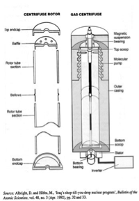
Figure 1. Schematics showing a supercritical Zippe-type centrifuge with two-rotor tubes and one bellows, a design with similarities to the IR-6 centrifuge. The type of bellows in the schematic, with an outward pointing convolution, is not the same as found in Iranian bellows, which have an inward pointing bellows, as can be seen in the video.
The video confirms that compared to the practices in Iranian centrifuge facilities in the 2003-2006 period, Iran takes much better care with respect to cleanliness, subsequently avoiding damage to centrifuge parts and subassemblies. This change is also apparent in earlier videos of the ICAC taken before it was destroyed.
IAEA surveillance cameras are not identifiable in the video, as would be required under the Joint Comprehensive Plan of Action (JCPOA). They may not be visible or may have been installed after the video was filmed. Nonetheless, a key question is how many advanced centrifuge components Iran has produced, how many advanced centrifuges has Iran assembled, and where they and the components are located. Verifying that number is likely to be challenging, further complicated by Iran’s decision to remove relevant IAEA cameras altogether in early June 2022.
Somewhat surprising is the small number of staff in the video. In earlier centrifuge assembly workshops, many personnel were typically present. This lack of personnel may reflect low levels of operation but also reluctance of personnel to be seen in a public video.
IR-6 Centrifuge
The predominant type of centrifuge shown in the video is the IR-6 centrifuge, probably Iran’s most promising advanced centrifuge design. However, the video shows that Iran has worked on changes to the design in recent years, and this centrifuge may still be under development, despite the deployment of several production-scale cascades at Natanz and Fordow.
According to the design information provided by Iran in 2015 under its JCPOA declarations, the IR-6 centrifuge was basically a larger diameter IR-2m centrifuge with carbon fiber, also called composite, rotor tubes, flat, carbon fiber end caps, and one difficult-to-make carbon fiber bellows. The rotor assembly, including two rotor tubes, a bellows, a baffle, and end caps, has the basic dimensions of 200 millimeters internal diameter and 1110 millimeters internal length. 6 As a fallback in 2015, Iran declared the shorter IR-6s which would be a single rotor cylinder, 200 millimeter internal diameter and 630 millimeter internal length, but with no bellows. In general, centrifuges with single rotor tubes are easier to manufacture and operate. At the same time, centrifuges with one bellows are significantly easier to balance than those with two or more bellows.
The video suggests that parts of the IR-6 design have changed since 2015, perhaps indicating ongoing problems in these centrifuges. The video shows domed end caps rather than flat ones. 7
More significantly, Iran may have changed, or may be changing, the bellows design. It is well known that Iran has encountered problems successfully making carbon fiber bellows, a choice initially dictated by past difficulties procuring the more strictly—or at least more successfully—controlled maraging steel, the more traditional bellows material for centrifuges derived from Pakistani designs, including the IR-1 and IR-2 centrifuges.
Despite Iran’s past difficulties to procure maraging steel, the video shows what appear to be IR-6 bellows in storage cabinets that appear silver rather than black grayish, indicating metal instead of carbon fiber. Maraging steel is a logical candidate for these bellows given the speed requirements of Iran’s deployed advanced centrifuges, claimed to reach tangential speeds of up to 600 meters per second. This is partially confirmed by IAEA reporting. On January 23, 2021, the IAEA verified that Iran had started manufacturing metal bellows for IR-6 centrifuges for testing, which Iran plans to reinforce with carbon fiber. 8 It is possible that the new bellows use a lower quality maraging steel, requiring carbon fiber reinforcement, or use another metal other than maraging steel, also necessitating carbon fiber support.
Overall, this finding raises further questions about the status of Iran’s bellows efforts, including whether Iran is in fact making maraging steel bellows, and if so, where it is sourcing the maraging steel. Is it produced domestically or imported?
Video Tour
The following is a tour of several rooms in this new facility, where freeze frame images from the video are presented with expert comments.
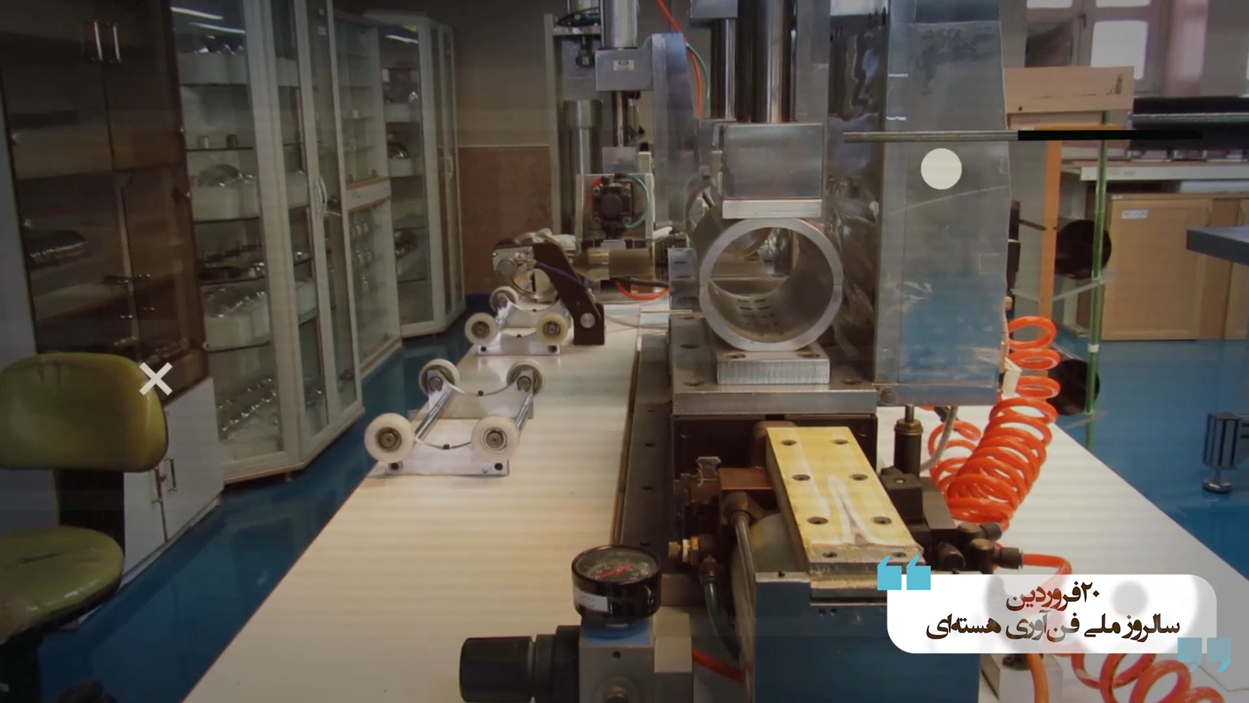
Figure 2. A general view of a small-scale assembly workshop. On the tabletop are support rollers for supporting cylinders in accordance with standard laboratory practices. Various centrifuge components are seen in glass cabinets. The machine in the center could not be identified.
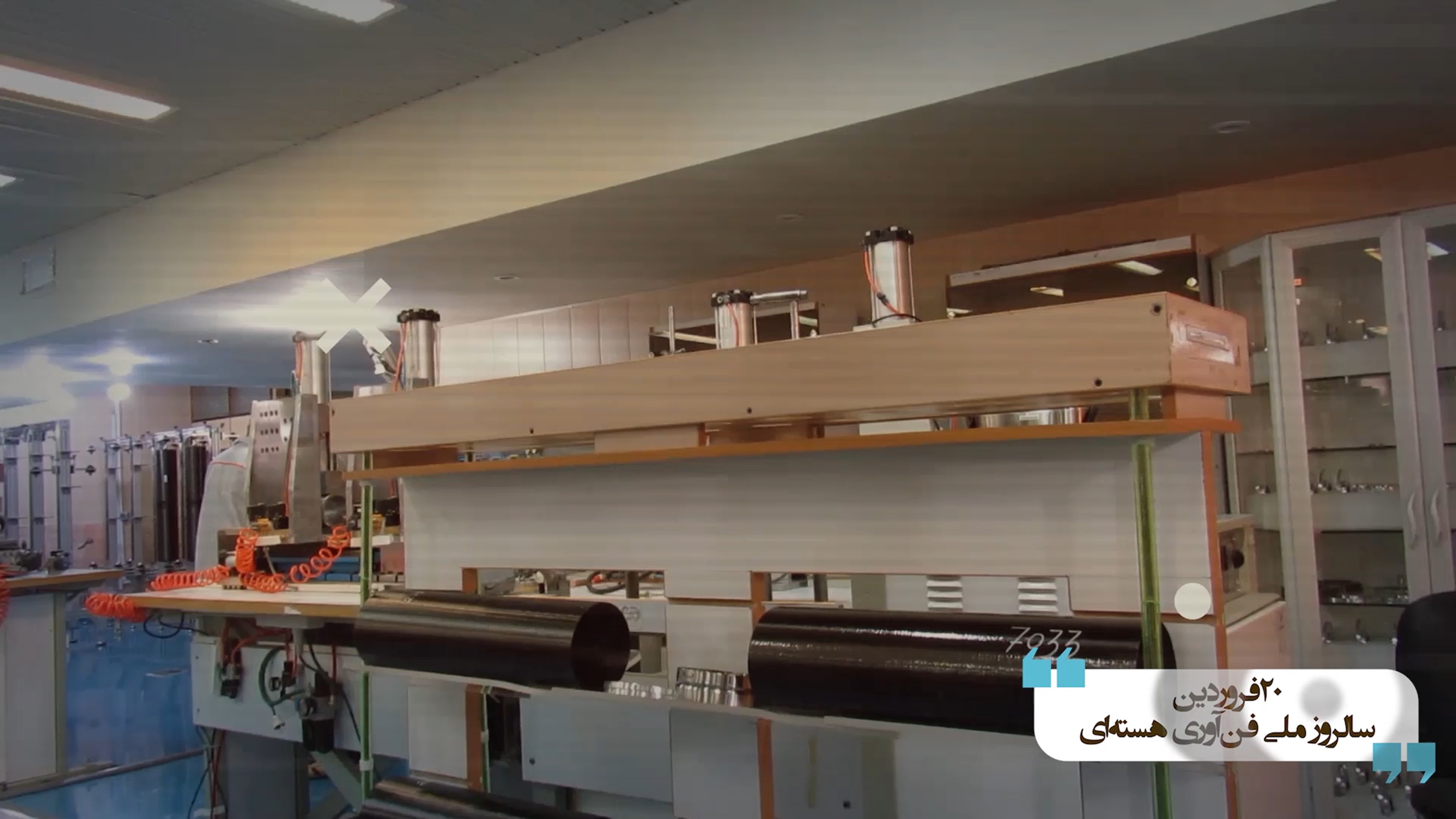
Figure 3. In same room as in Figure 2, two carbon fiber cylinders awaiting assembly. Between them is possibly a metal bellows, most logically made of maraging steel because of the relatively high speeds achieved by the advanced centrifuges.
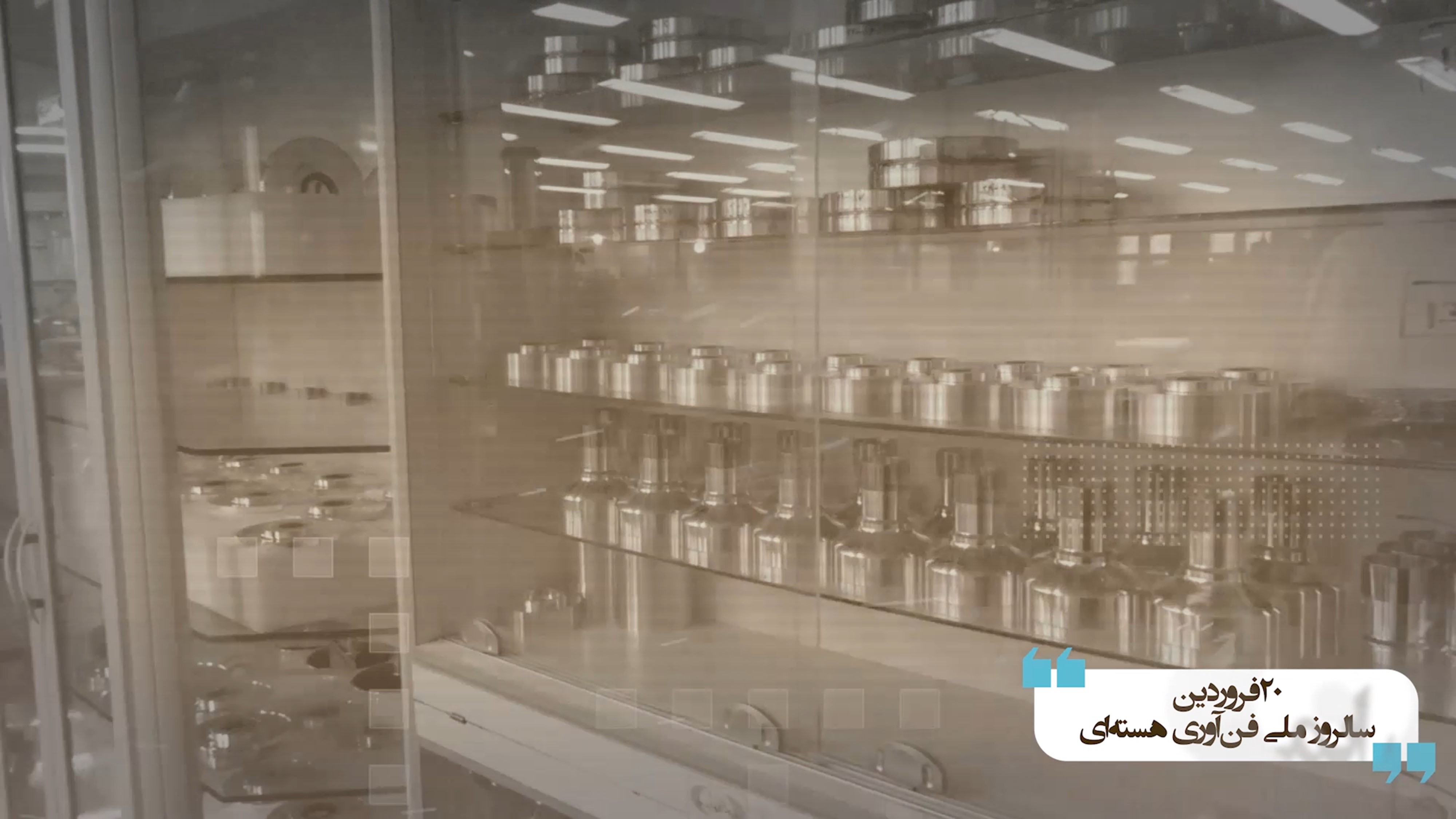
Figure 4. Two component storage cabinets. In the cabinet on the right side, on the upper two shelves are more metal bellows, again possibly made of maraging steel although high strength aluminum cannot be excluded. The lower two shelves also hold subcomponents, which have diameters slightly smaller than the bellows. One shelf may hold top cap metal inserts that hold the rotating magnet and catch the top end of the rotor when unintended rotor vibrations occur during startup and rotor failure. The other shelf may hold bottom cap metal inserts for holding the rotating elements of the drive and bottom bearing pin and ball. These subcomponents could be of high strength aluminum alloy or maraging steel. All of these components appear to have been degreased and cleaned, hence stored in a closed cabinet.
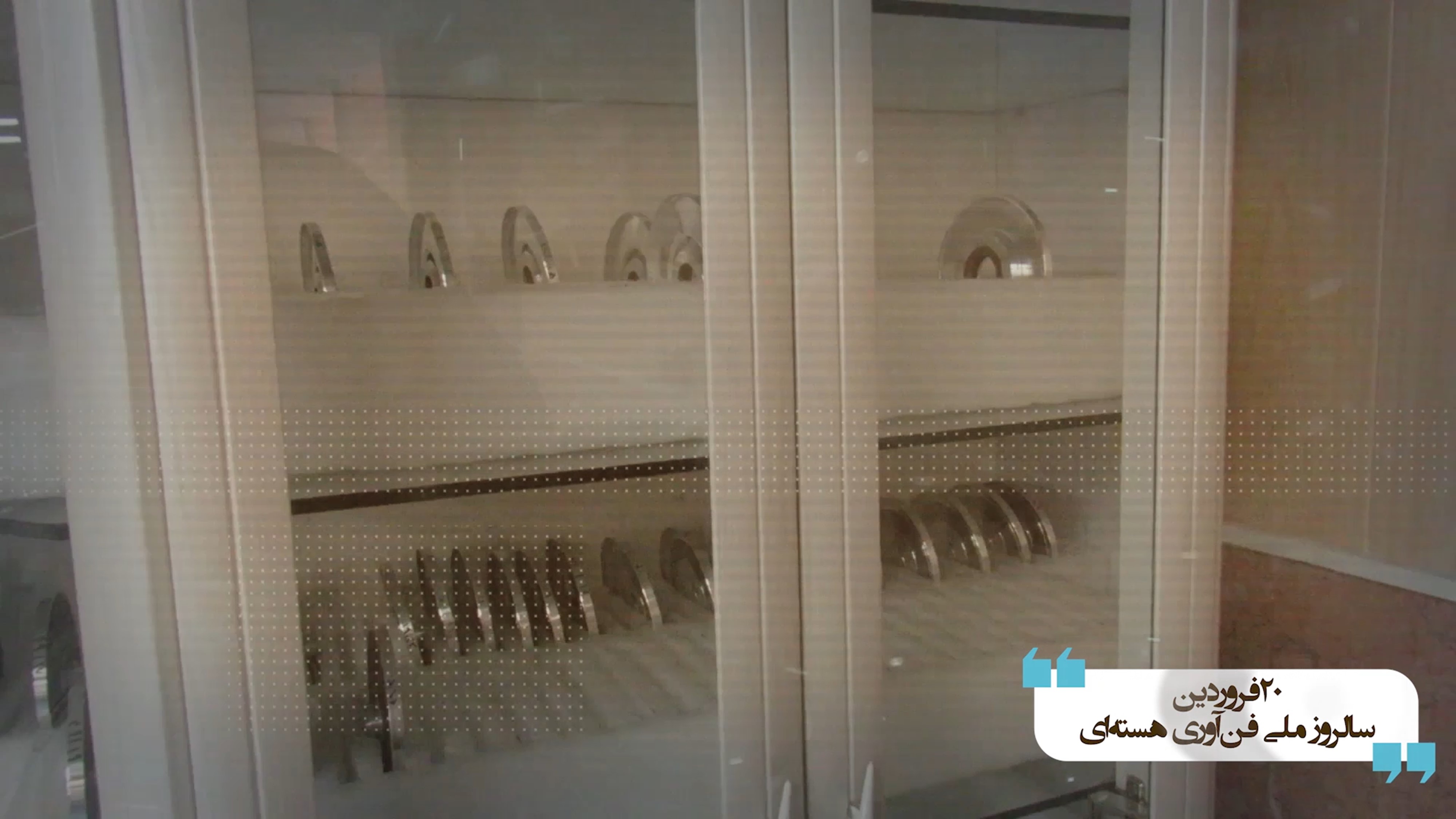
Figure 5. This cabinet contains a stock of centrifuge subcomponents. At first glance, they look like baffles made from metal rather than carbon fiber. Baffles are inserted in the rotor to create the counter-current gas flow and to isolate the top scoop extraction chamber. Note that the subcomponent is made of metal and not a carbon composite, and is likely made of maraging steel or high strength aluminum. They could also be end caps made out of high strength aluminum, where they are inserted inside the carbon fiber rotor tube, providing strengthening.
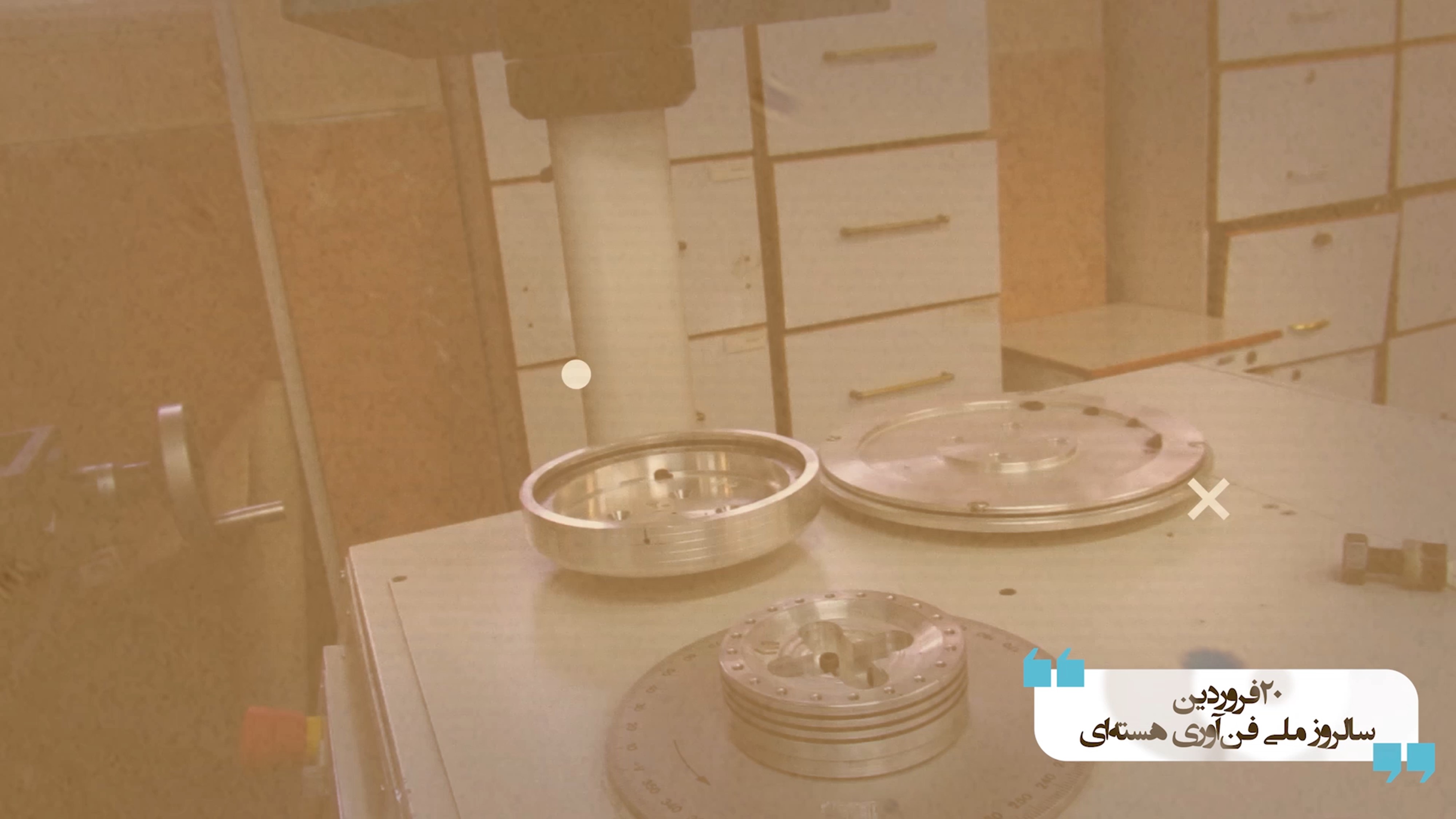
Figure 6. A photo with possible top and bottom end flanges of the outer casing, also known as the recipient.
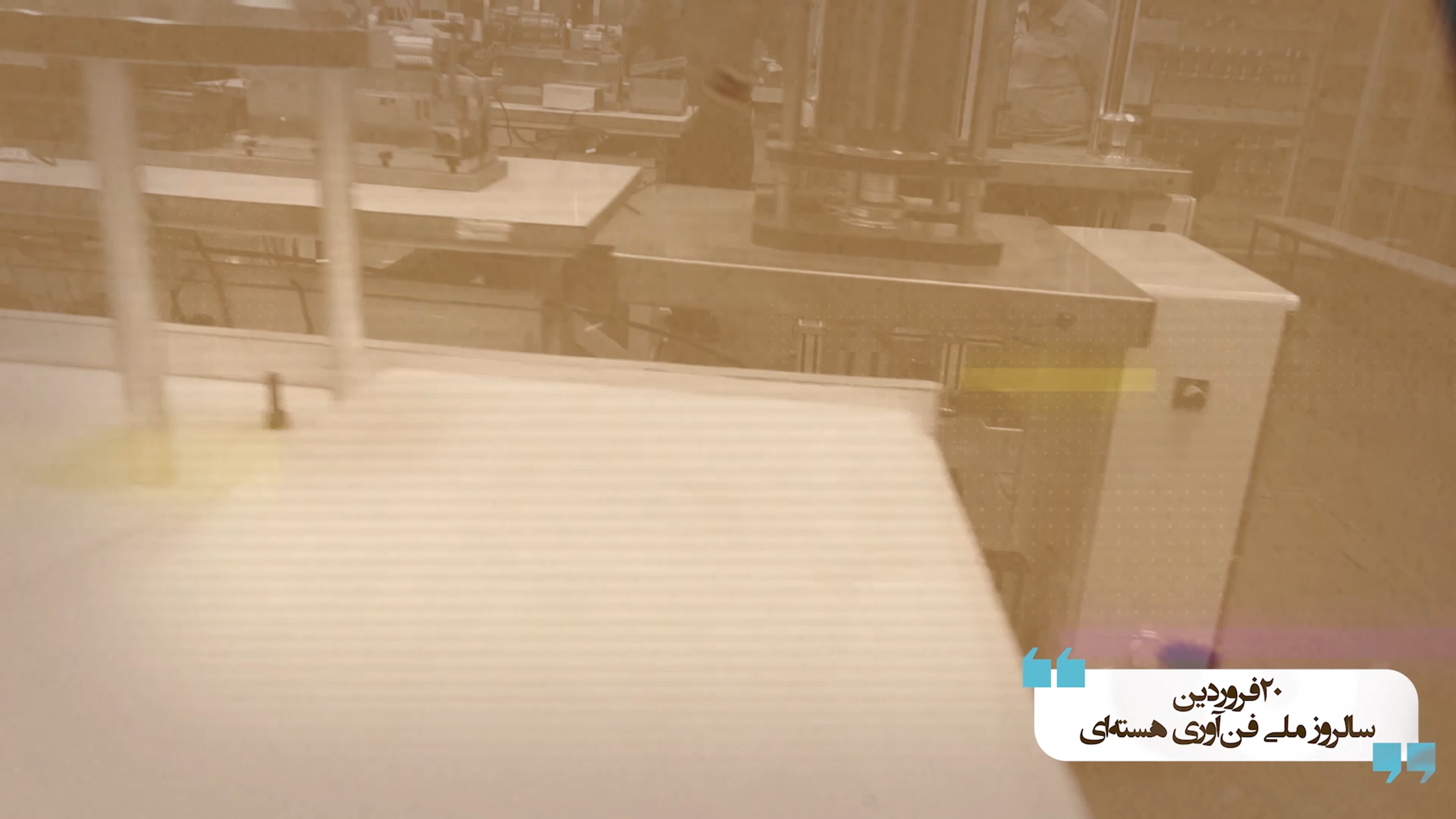
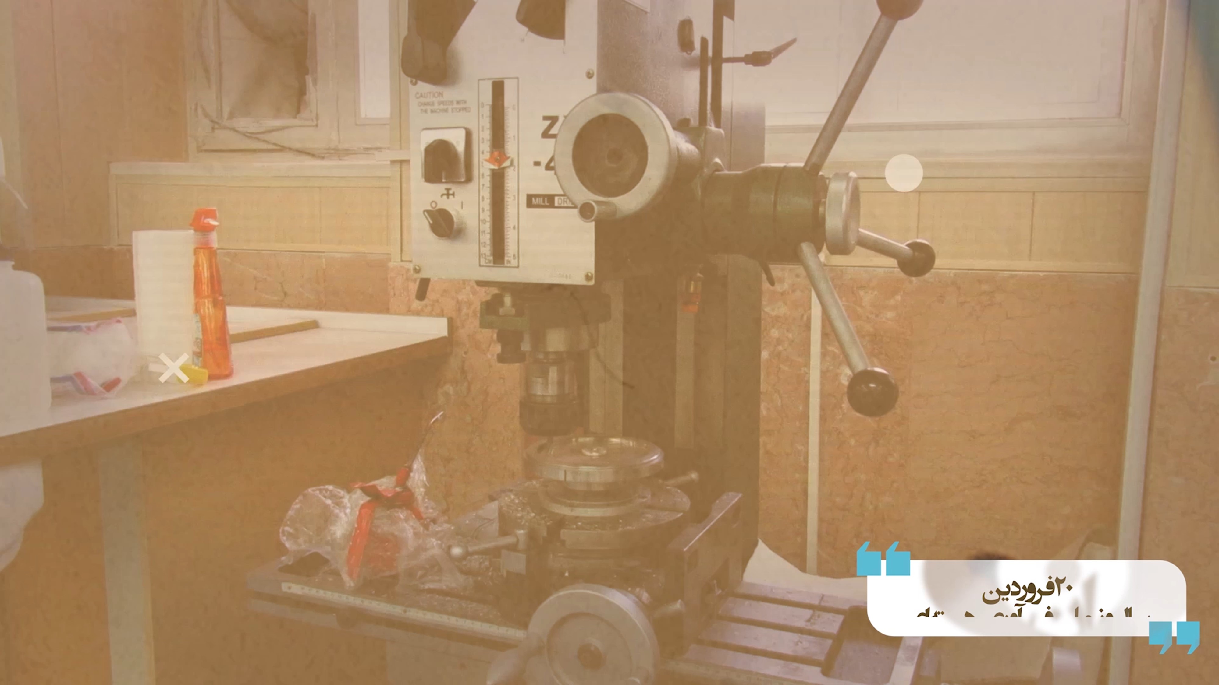
Figure 7. Top photo: A relatively crowded room showing equipment used in the assembly of the base flange, the motor housing and the bottom flange of the outer casing. Bottom photo: An old milling and drilling machine (also see right side of top image in figure 8); apparently, there is a need to drill holes and to remove some surplus metal during this subassembly operation.
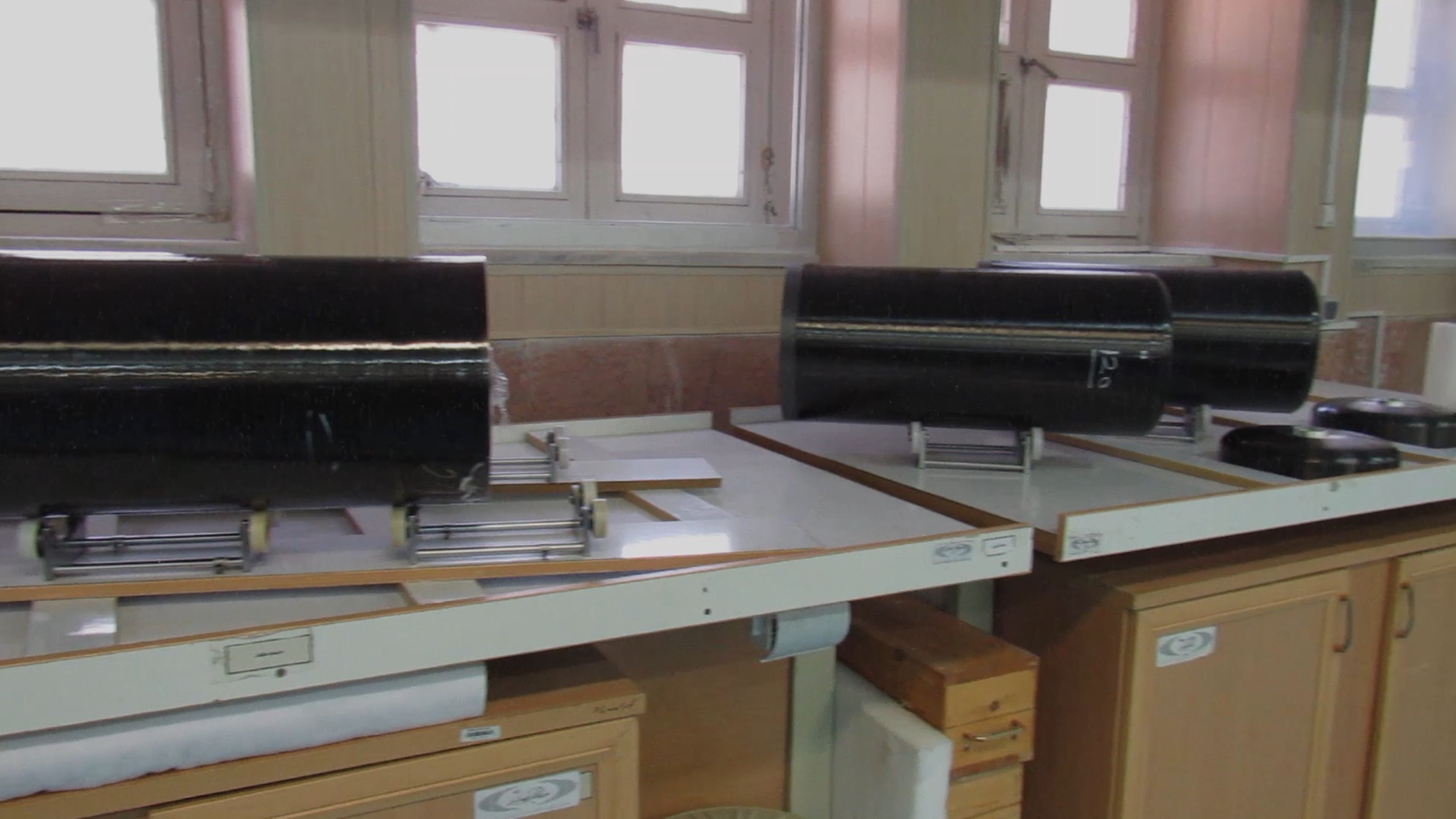
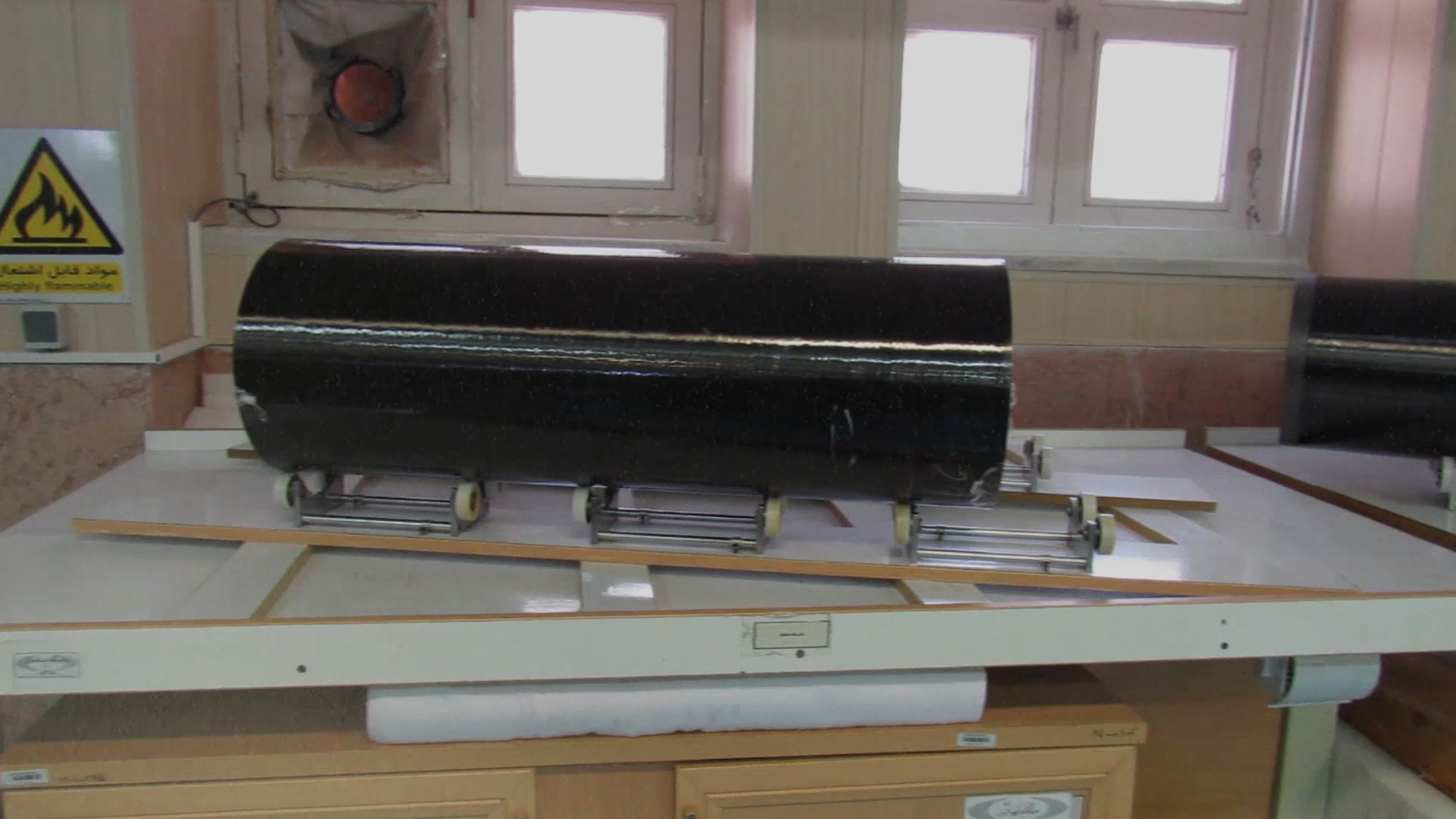
Figure 8. IR-6 rotor tubes on two adjacent work surfaces shown in consecutive freeze frames, panning from right to left. The top photo shows that the end of one rotor tube has been partly machined, likely for fitting purposes, and the other end holds a domed end cap (the machined end can also be seen in the partial rotor tube on the right side of the bottom image.) Accepting that the cylinder diameter is 200 millimeters then one can roughly measure the length from the photo as about 600 millimeters, as expected). Note that in the top image there are two domed top caps on the table awaiting to be fitted onto the cylinders. The caps appear to be made from carbon fiber and have a metal insert. The windows are consistent with being in a half-basement, such as found in the Natanz administration building (see text).
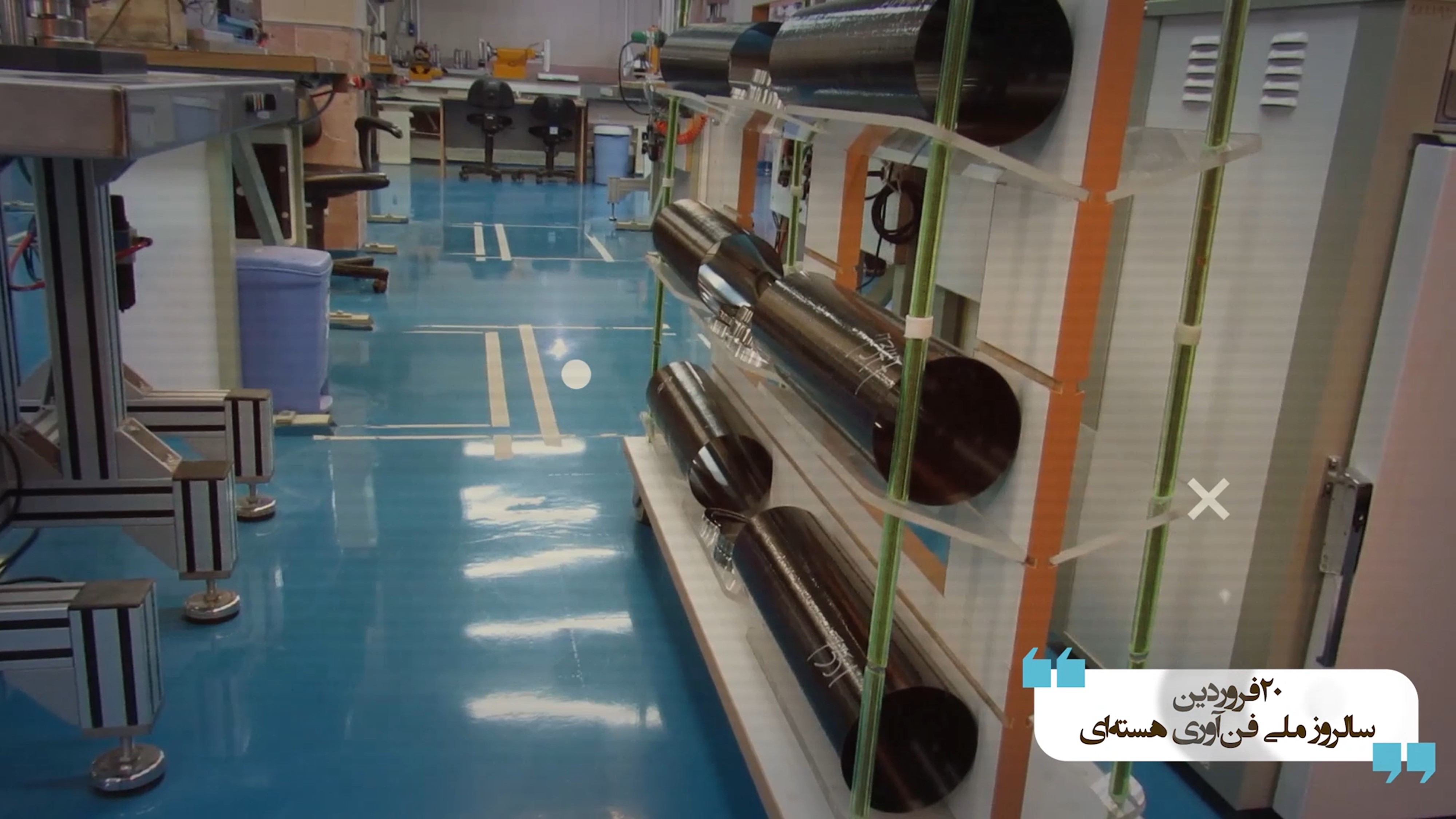
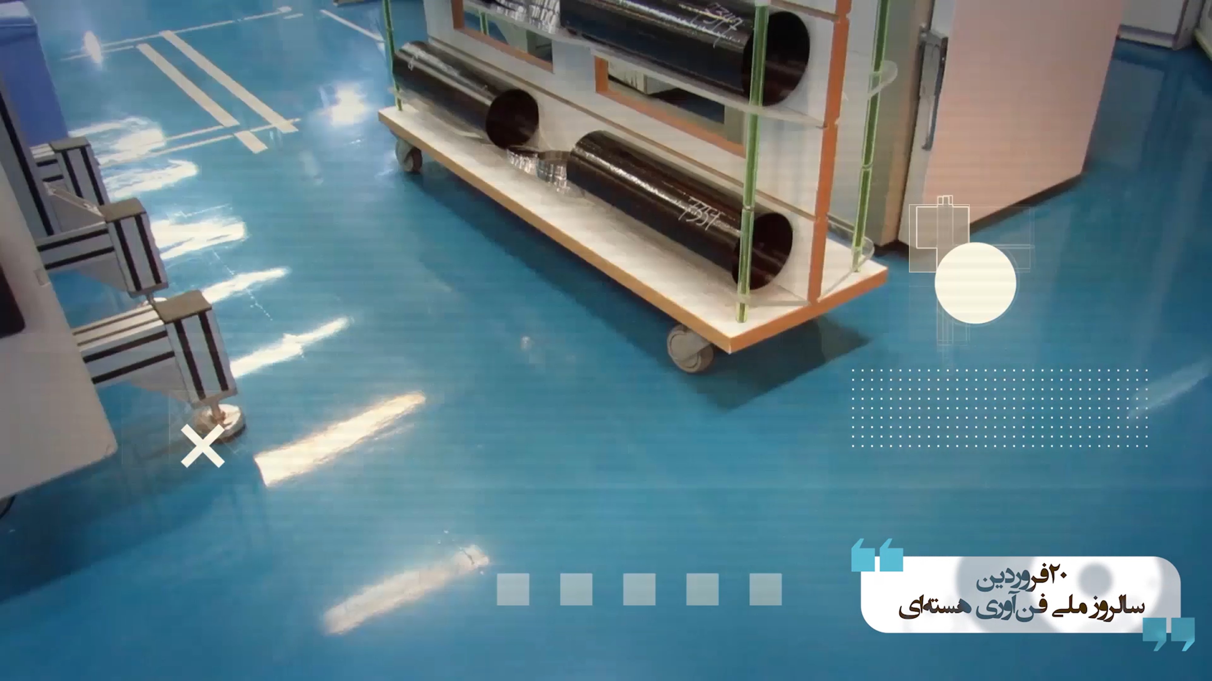
Figure 9. Photos showing how the cylinders are handled and moved around a subassembly shop.
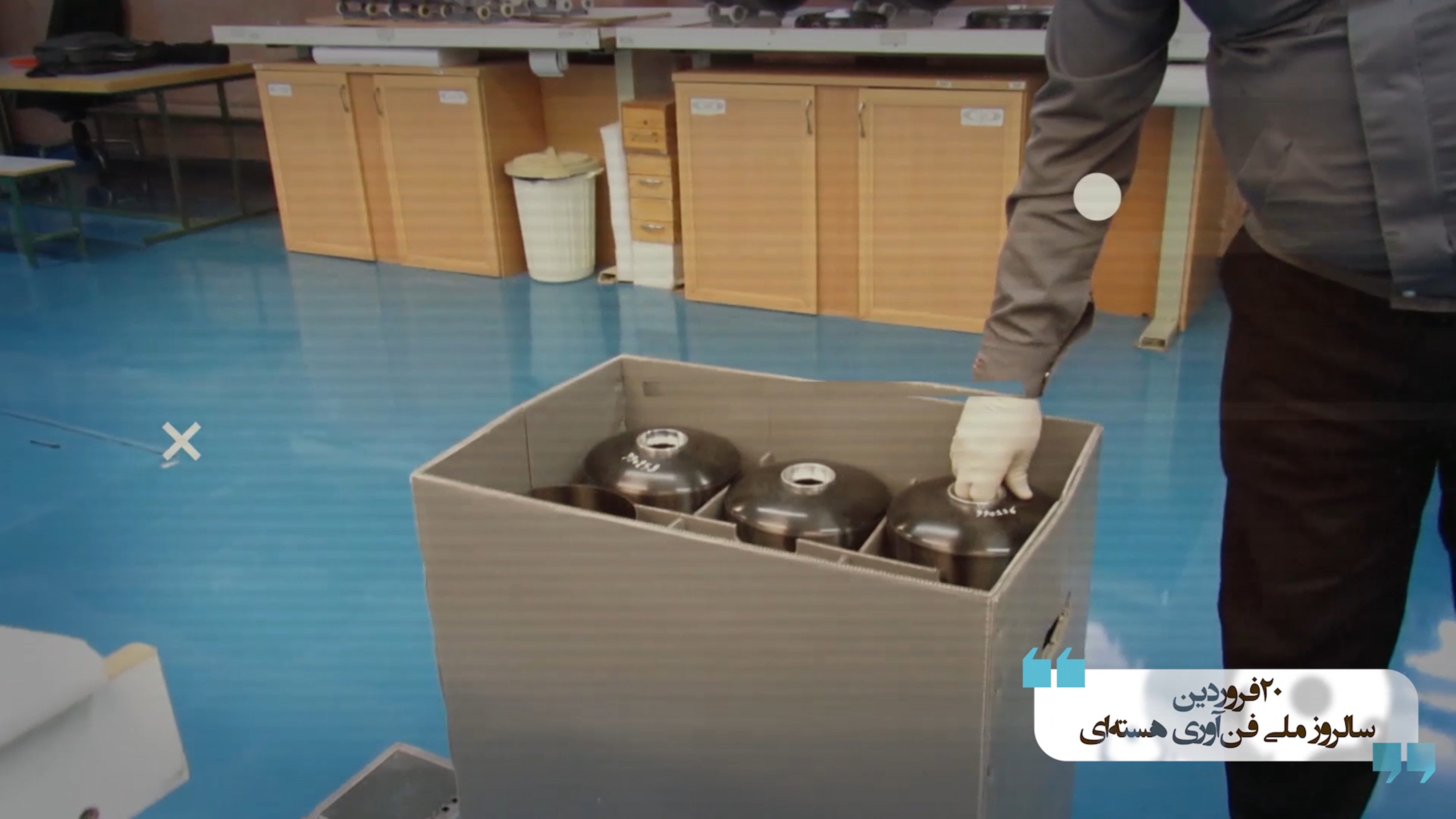
Figure 10. Visible is a carton box large enough for containing IR-6 rotor tubes and top caps. The top caps are domed with a flat section in the middle. Using the man’s leg as a guide, the box appears to be about 800 millimeters in depth. Note that the end caps do not have rotating magnets installed at this point, although they look like they have a metal insert to hold the magnet. (The magnet holder, absent the magnet, may be used to hold the rotor vertically while checking its balance and straightness (see below.))
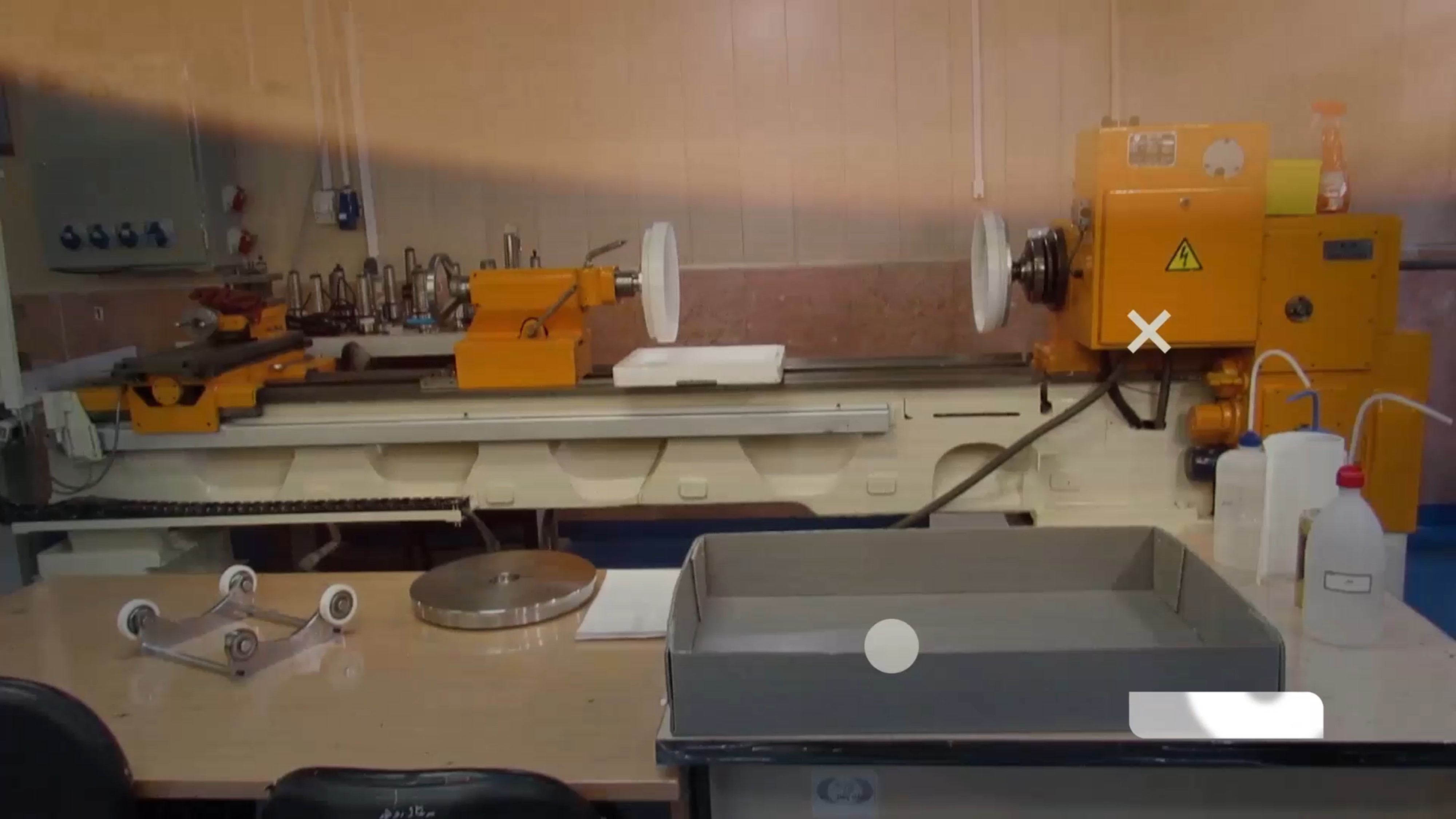

Figure 11. Measuring and balancing equipment used to quality check incoming rotor tubes and other components. It can hold a rotor tube horizontally to check its dimensions, such as length, diameter, ovality, and straightness, and also ensure it is balanced.
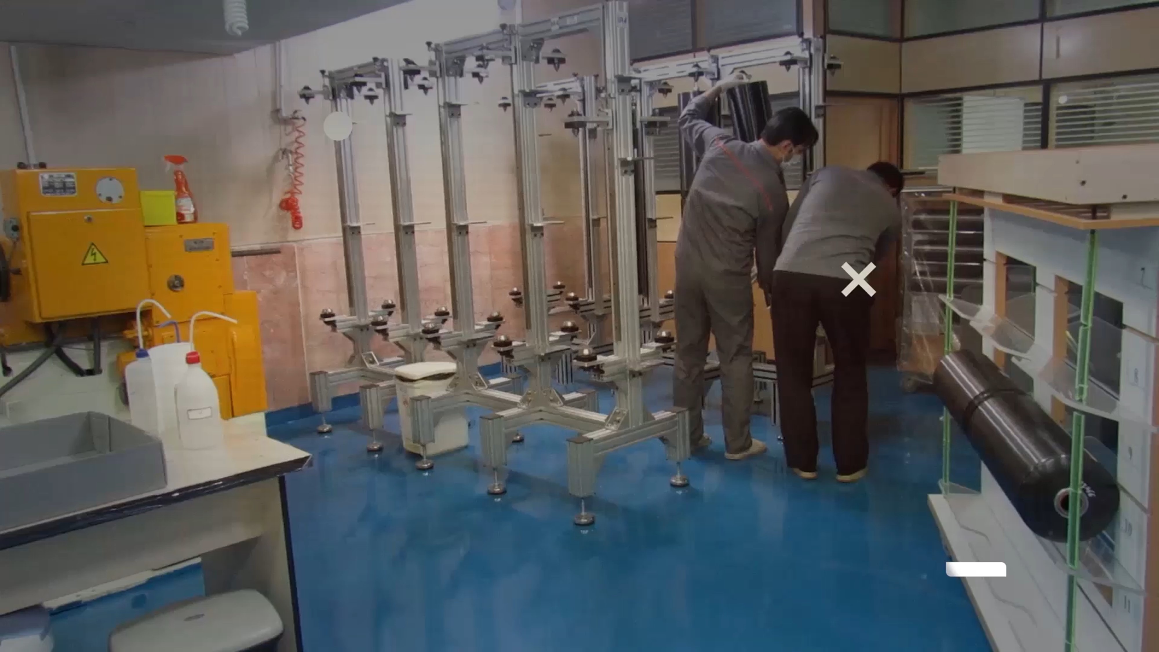
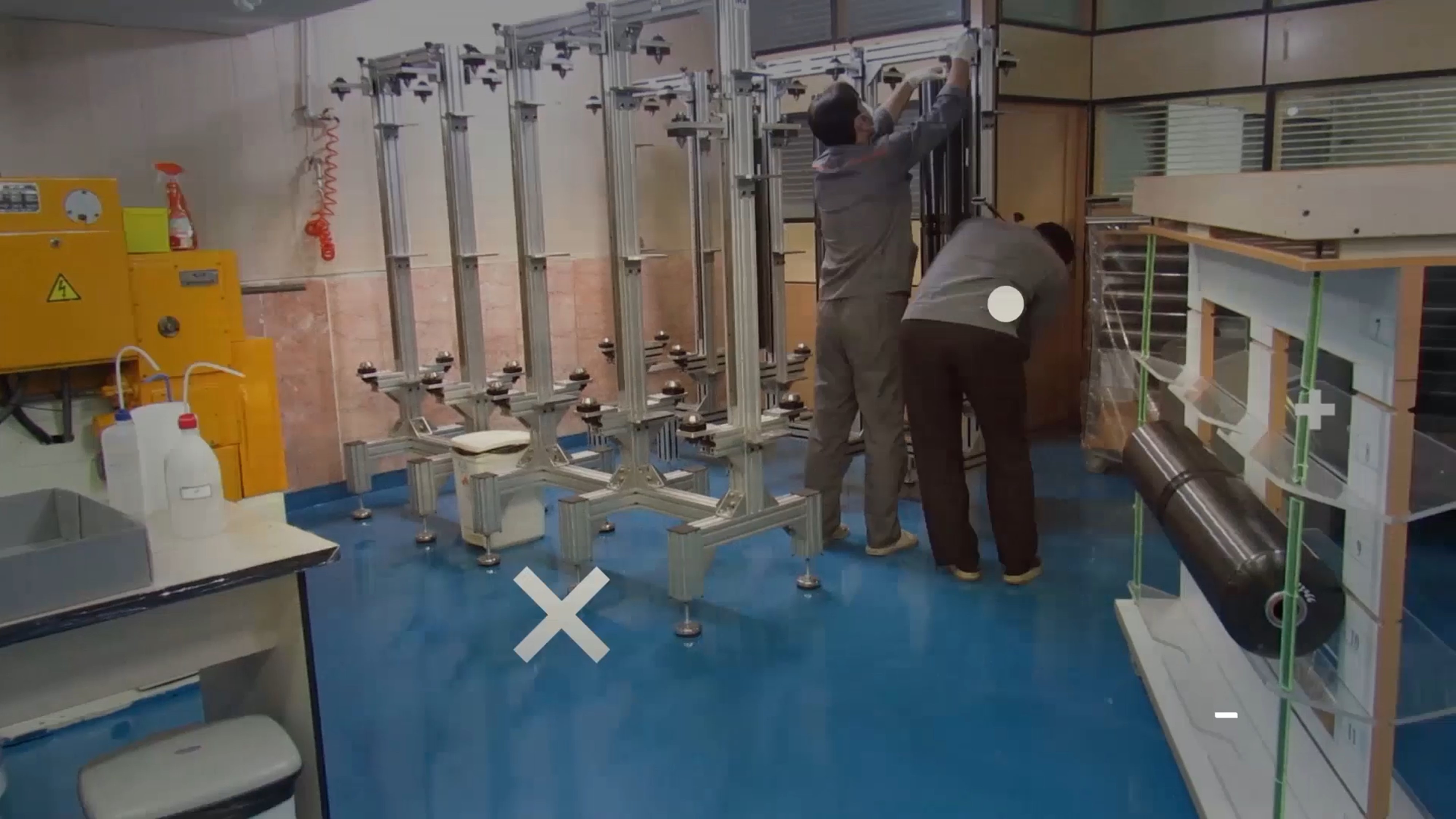
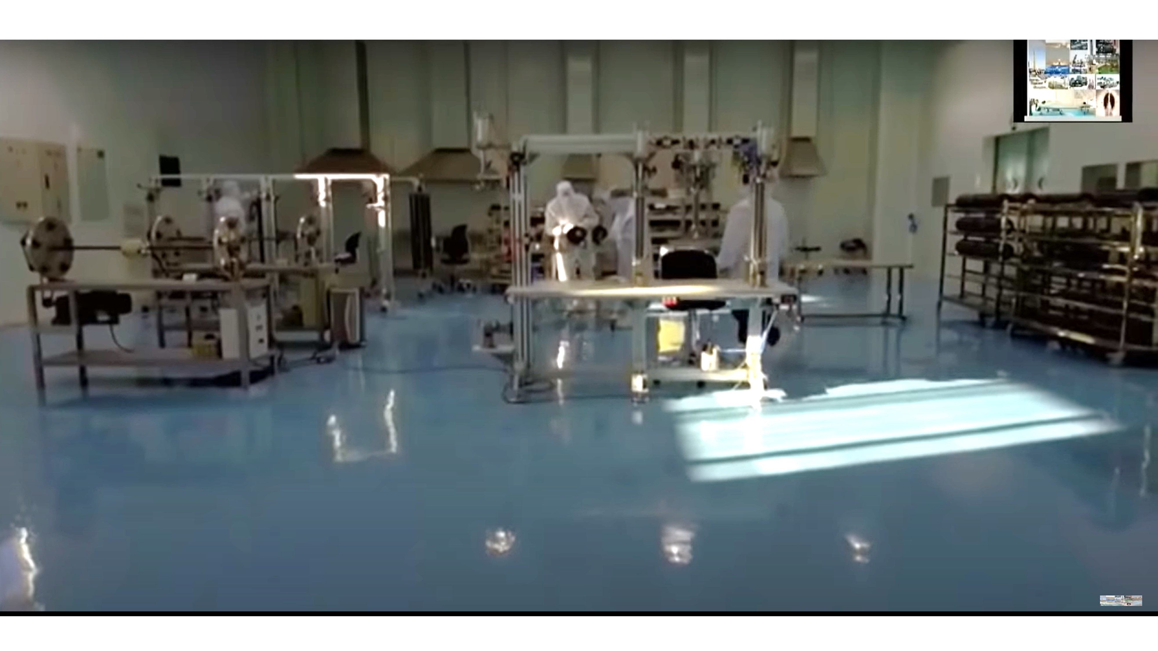
Figure 12. The top two photos show two workers loading an IR-6 assembled rotor vertically into a rotor straightening and balancing rig. Three or four rotor assemblies are visible in the photo. There are 20 rigs in total, some with different heights. The two personnel may be working with more than one rig at the same time. The workers must ensure that the rotor assembly is straight, which can be done by slowly rotating the assembly, while using probes and simple adjustments. For comparison, the bottom photo is of a similar, albeit far larger, room in the destroyed Iran Centrifuge Assembly Center, showing straightening and balancing equipment and rigs, racks of rotor tubes, and workers in protective, sanitary clothing. Such clothing is absent from personnel in the video, perhaps consistent with staged activities conducted for the video.
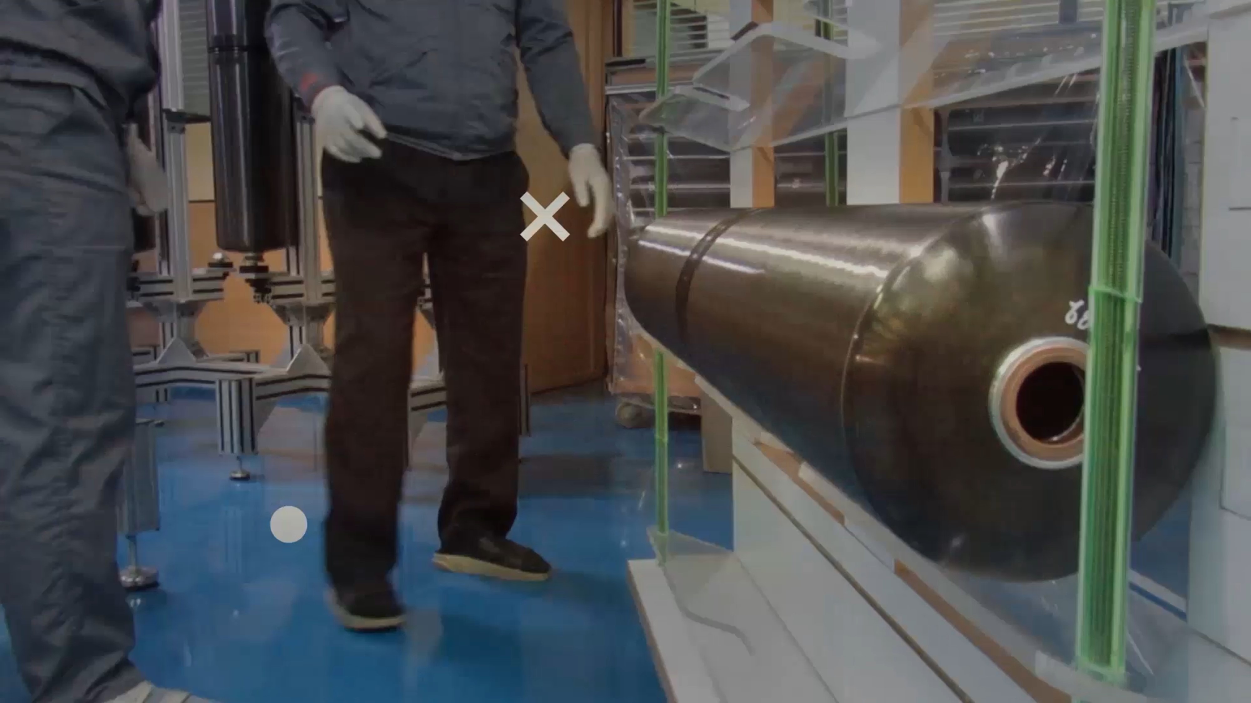
Figure 13. A close-up of an assembled IR-6 rotor assembly. Note that the rotating magnet, possibly made from cobalt samarium, is inserted into the metal insert of the top end cap. It is unclear if a bottom bearing pin and motor armature have been attached to the bottom of the rotor assembly. The bellows looks darker than those on the shelf made from metal, but the lighting complicates a determination of the bellows being made from carbon fiber instead of metal. However, perhaps these are carbon fiber strengthened metal bellows, e.g. overwrapped metal bellows, with the color of the carbon fiber overwrap.
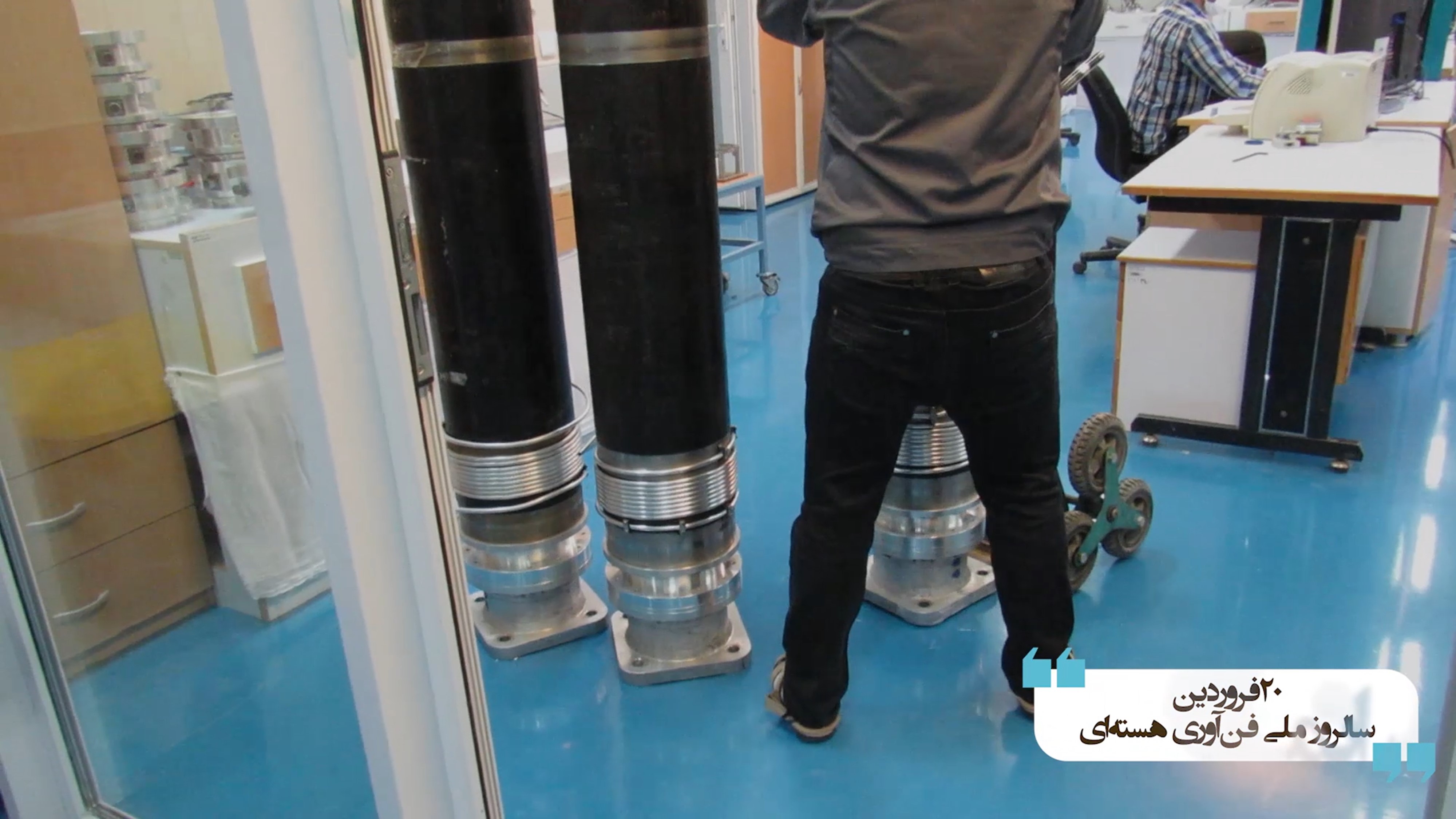
Figure 14. The image is a view of the bottom half of recipients and their base, showing the cooling water coils around the bottom of the recipient. The cooling is used to remove surplus heat from the rotor and to set up the temperature gradient along the rotor to stimulate the internal uranium hexafluoride gas flow. Stacks of motor housings may be visible in the left top of the top photo.
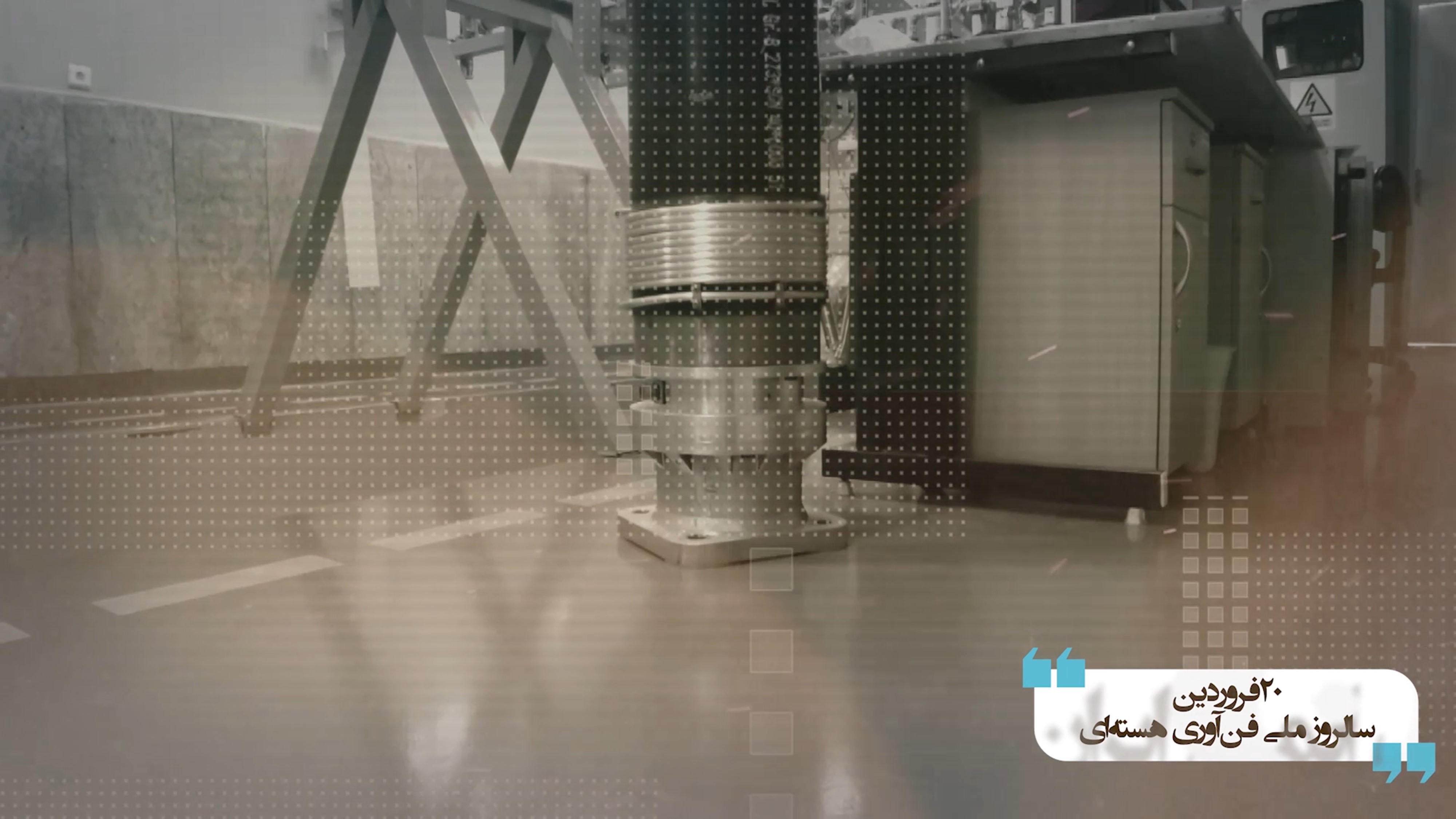
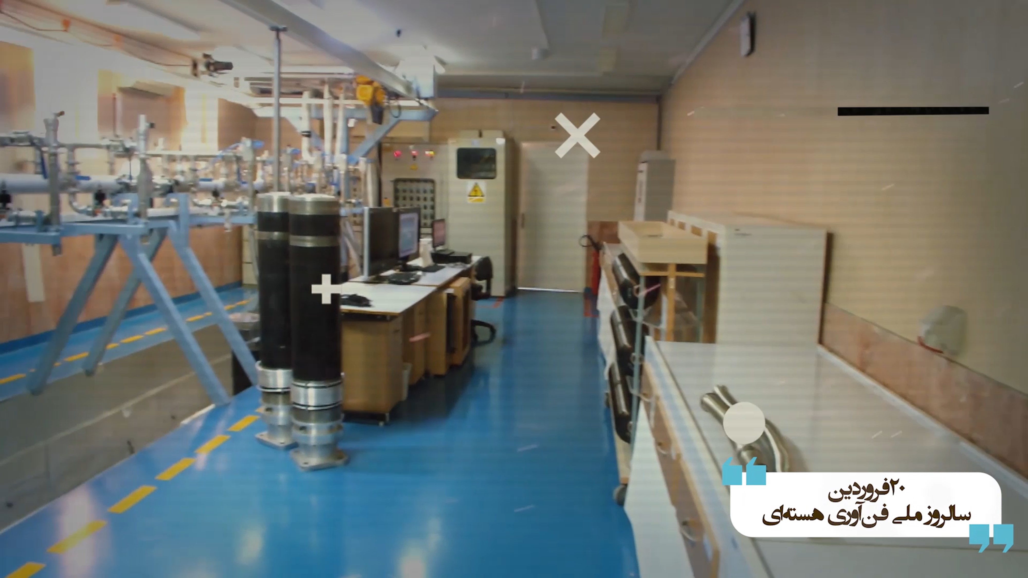
Figure 15. The video shows preparation for the installation of the centrifuge test stands in a testing pit. In the top photo, visible is the base flange of the centrifuge which will be bolted to the floor. The two IR-6 centrifuges in the bottom photo are awaiting lowering into the test pit, located to the left. Three rotor assemblies are visible along the right wall. The outer casings appear to be made of carbon steel rather than aluminum. Carbon steel casings have the advantage of being less expensive than aluminum ones, leading to frequent use in centrifuge programs, but carbon steel corrodes more easily, making aluminum preferable in Iranian enrichment plants.
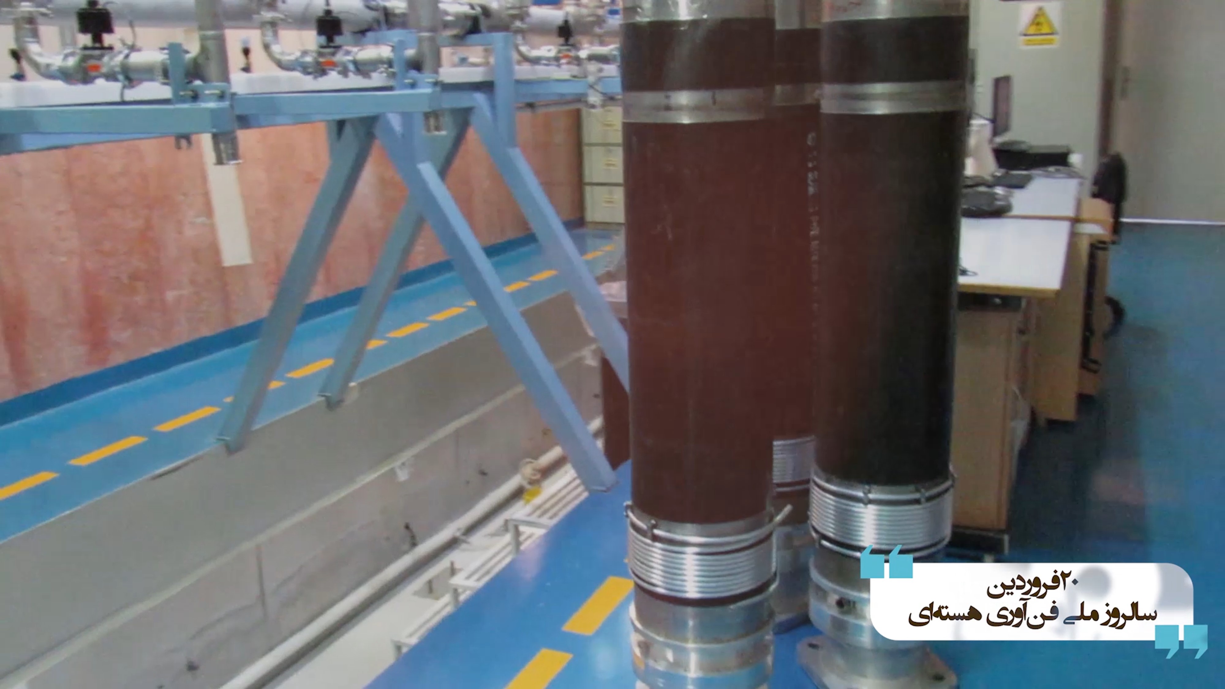
Figure 16. Three IR-6 test stands, with “case and base,” are awaiting to be lowered into a test pit.
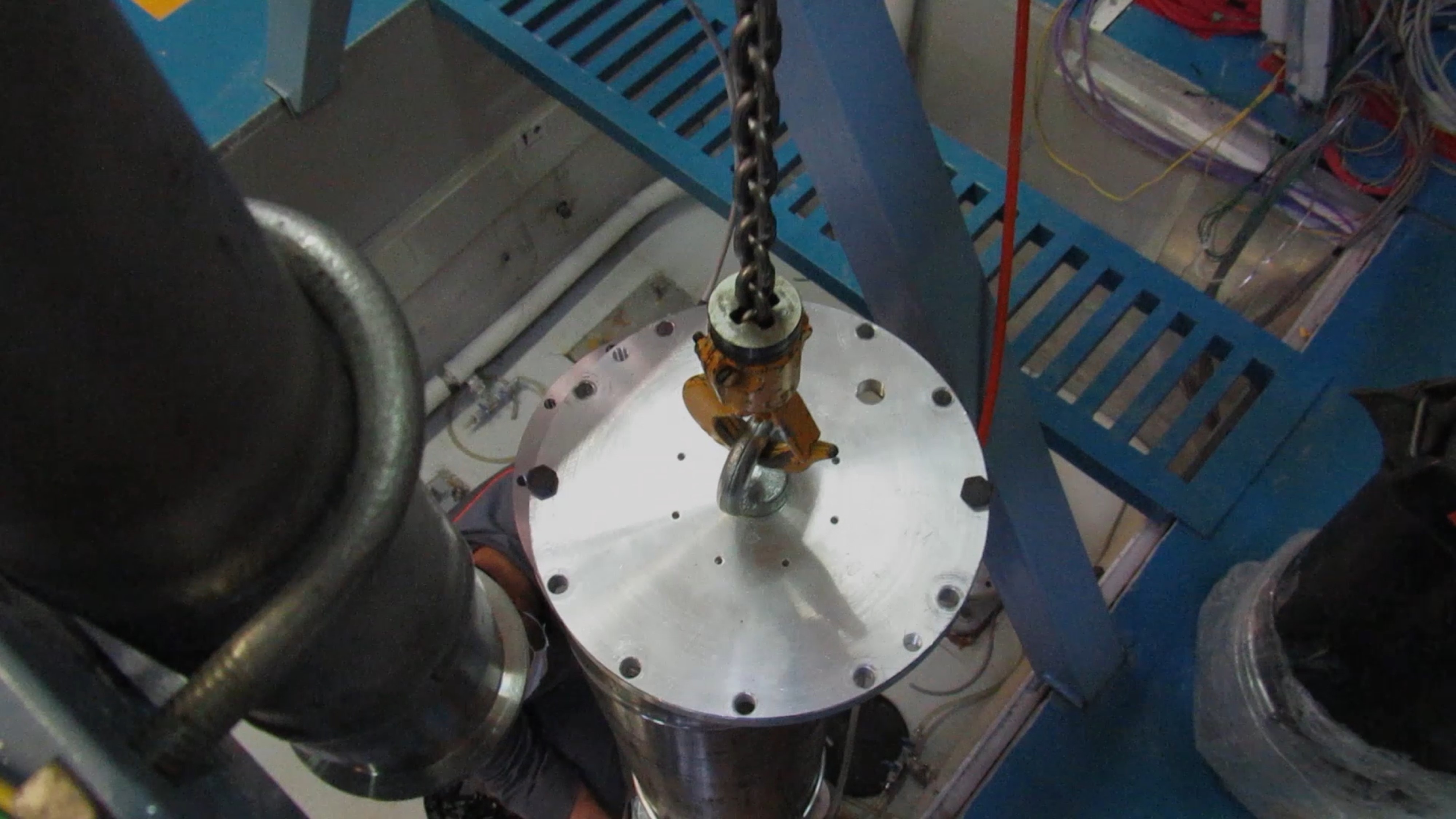
Figure 17. A close-up of the equipment used to lower the centrifuge test machines into the test pit.
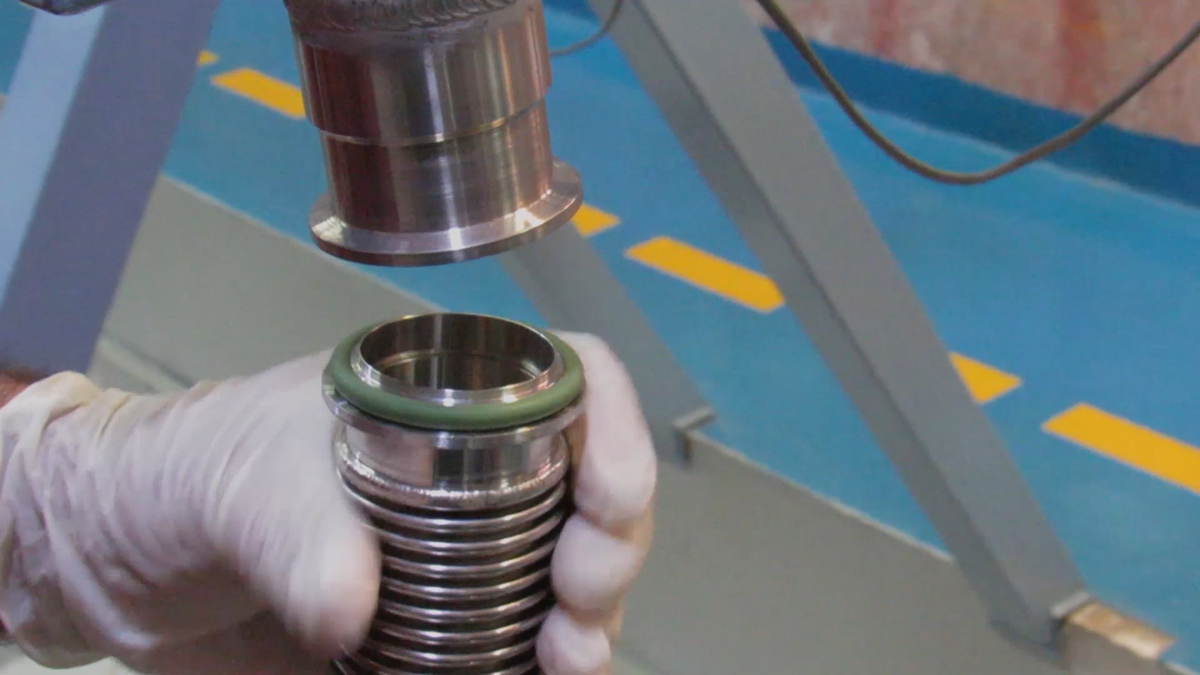
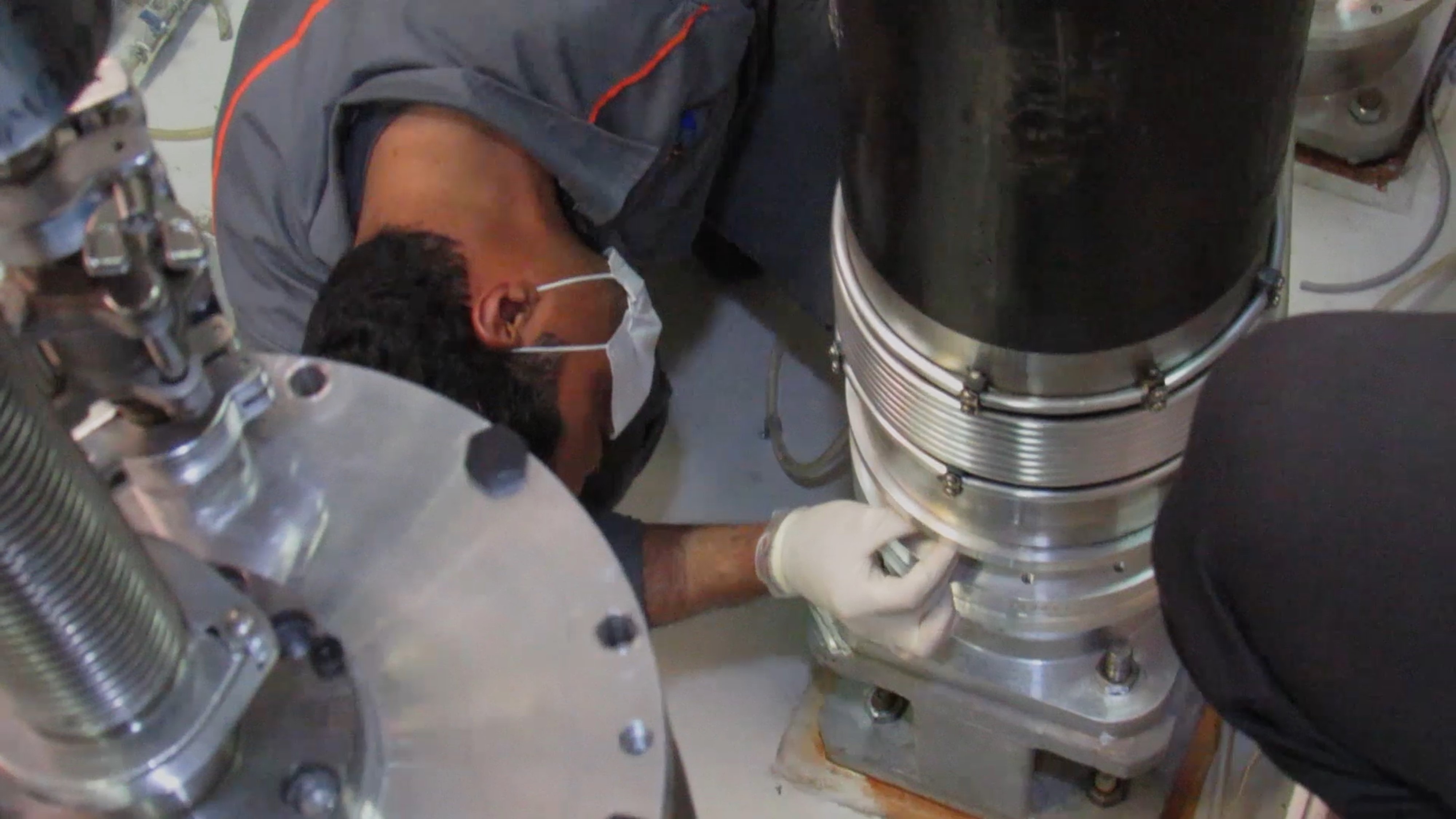
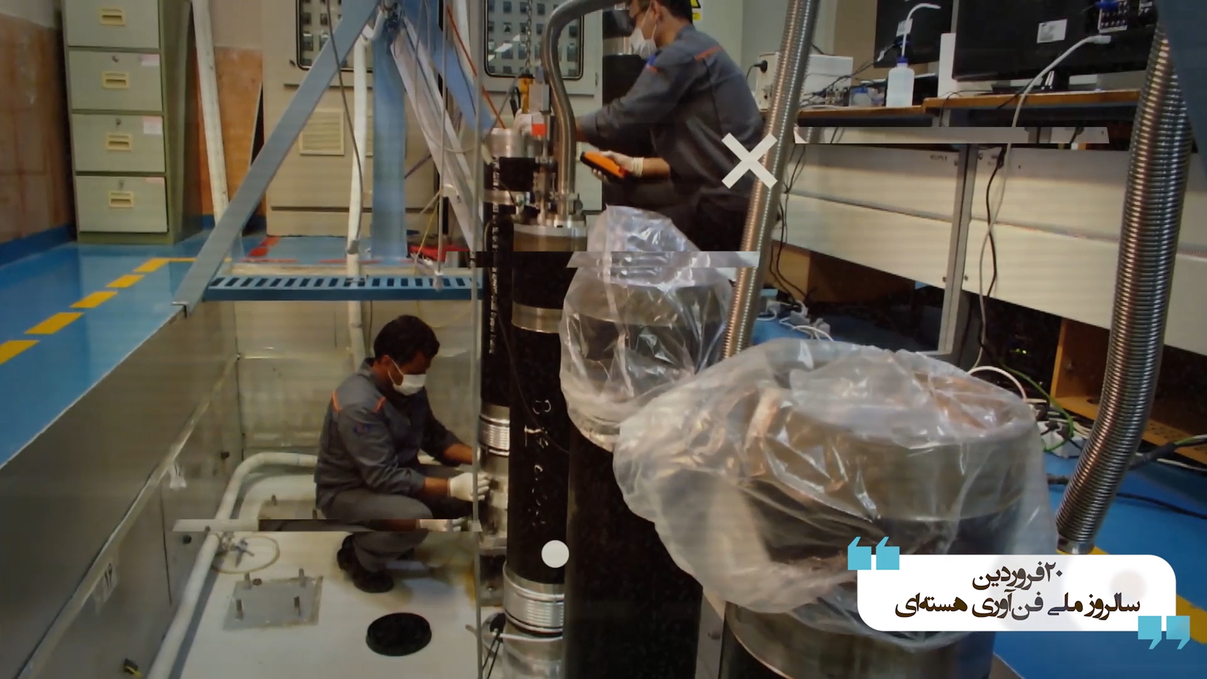
Figure 18. Installing the centrifuge case and base, including the outer casing, bearing housing, and motor drive housing, in a pit for mechanical testing or low speed spin tests related to quality control and assurance, likely for IR-6 centrifuges. The top photo shows the connection of the vacuum hose pipe to the top of the recipient, where a clamp is visible in a later image not included here. The middle and bottom photo shows the attachment of the motor drive unit to the bottom of the recipient.
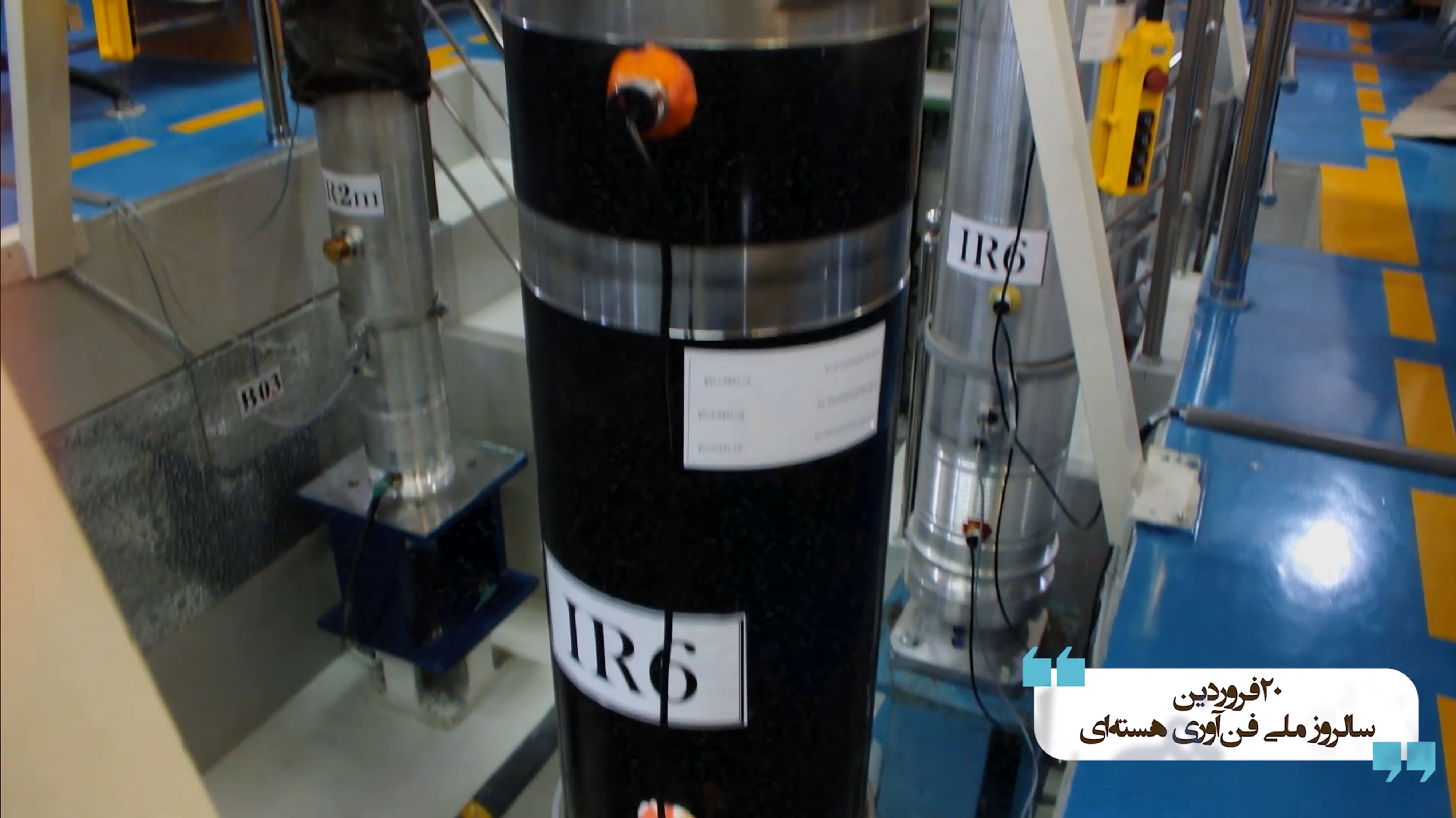
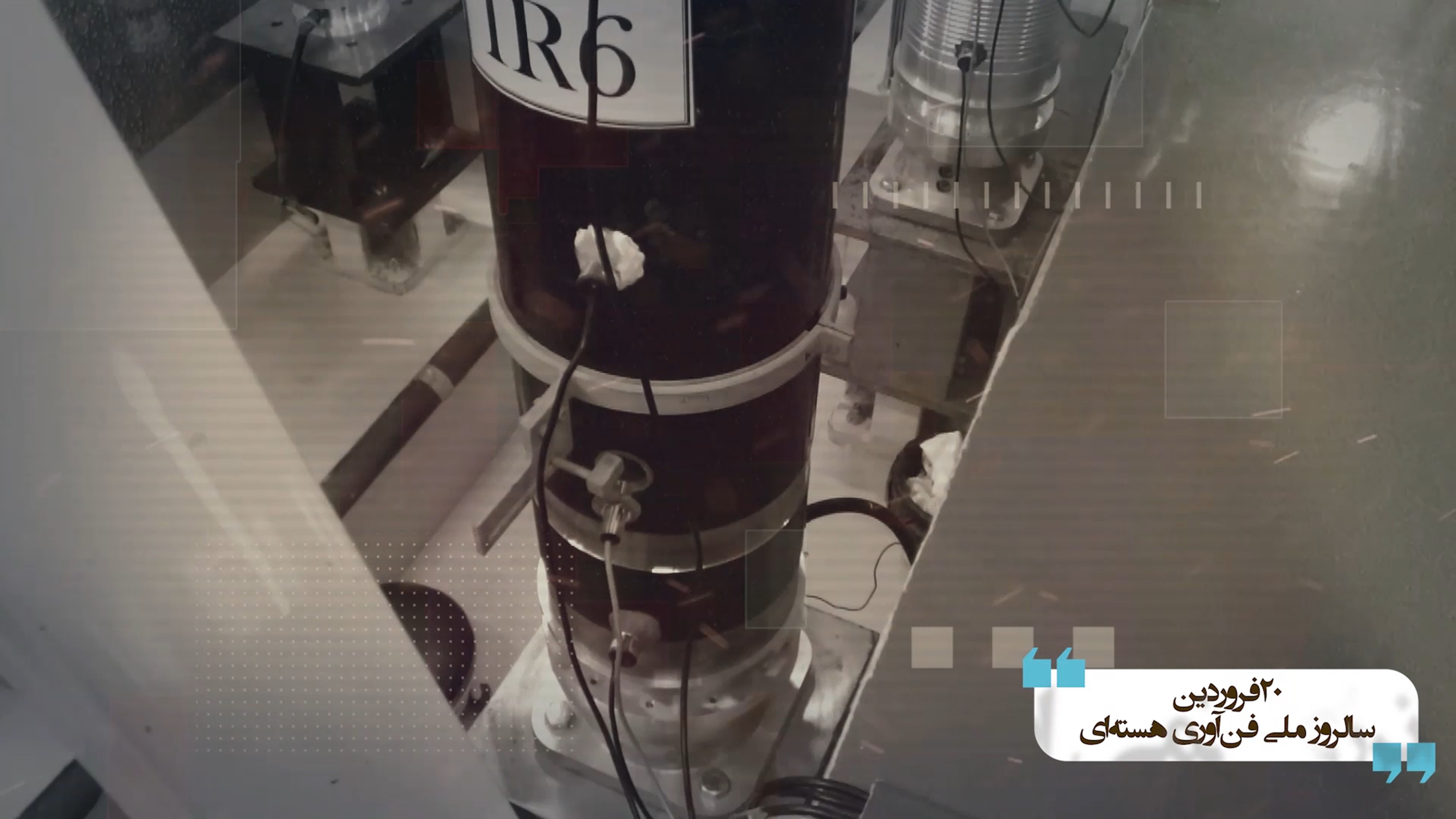
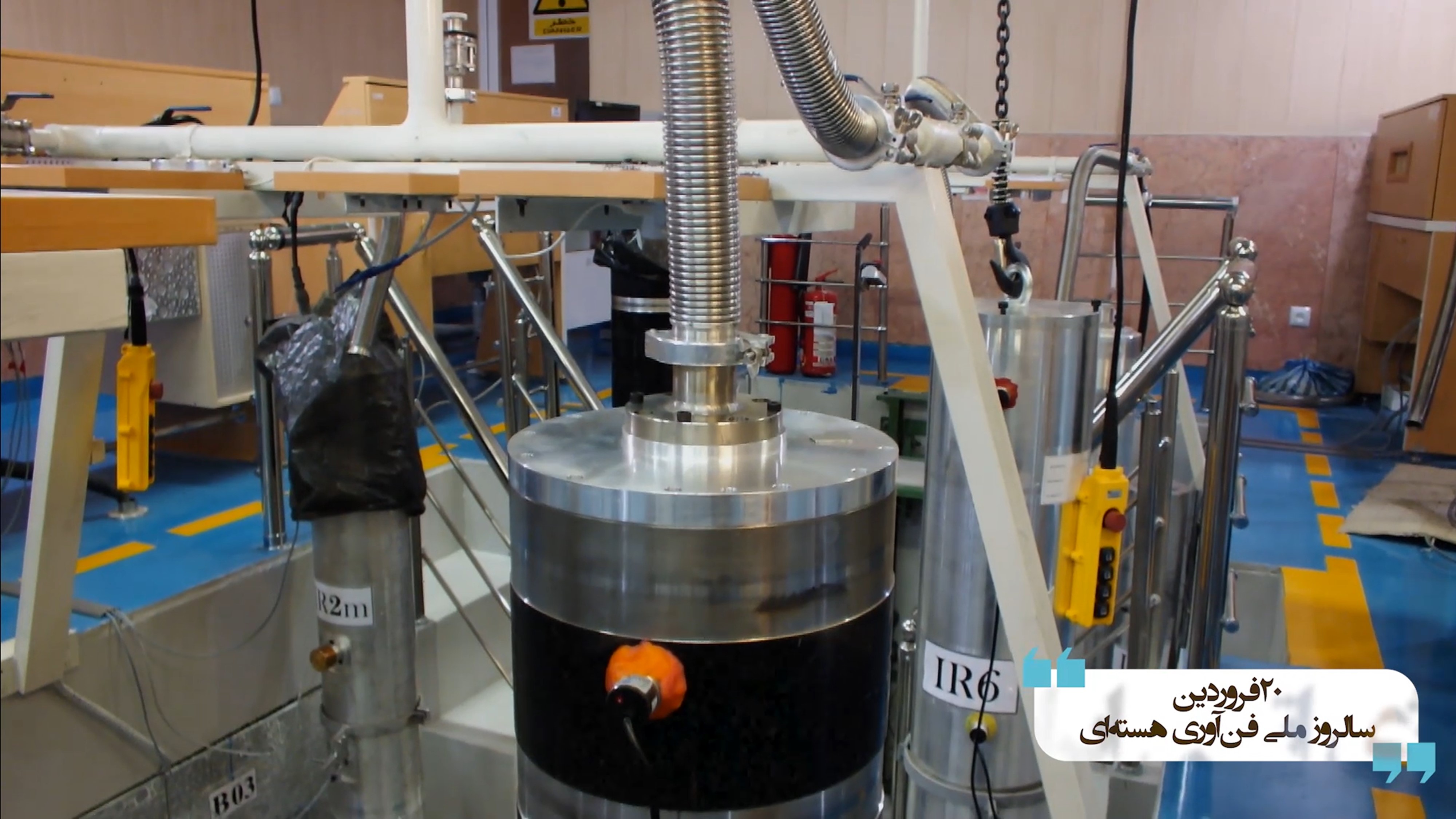
Figure 19. Top two images show close-ups of centrifuge test stands in a pit, labeled as the IR-6 centrifuge. Note that to the left of the IR-6 is an IR-2m machine test stand and to the right and slightly behind may be a version of an IR-6 machine with an aluminum outer casing rather than carbon steel. In the bottom photo, the IR-6 centrifuge is connected to vacuum piping and may be undergoing spin testing. The pit is marked B03, possibly related to location, and is not the same pit as in earlier images. In addition, the water coils appear to be missing. The labelling may reflect their use in other public videos released by the AEOI.
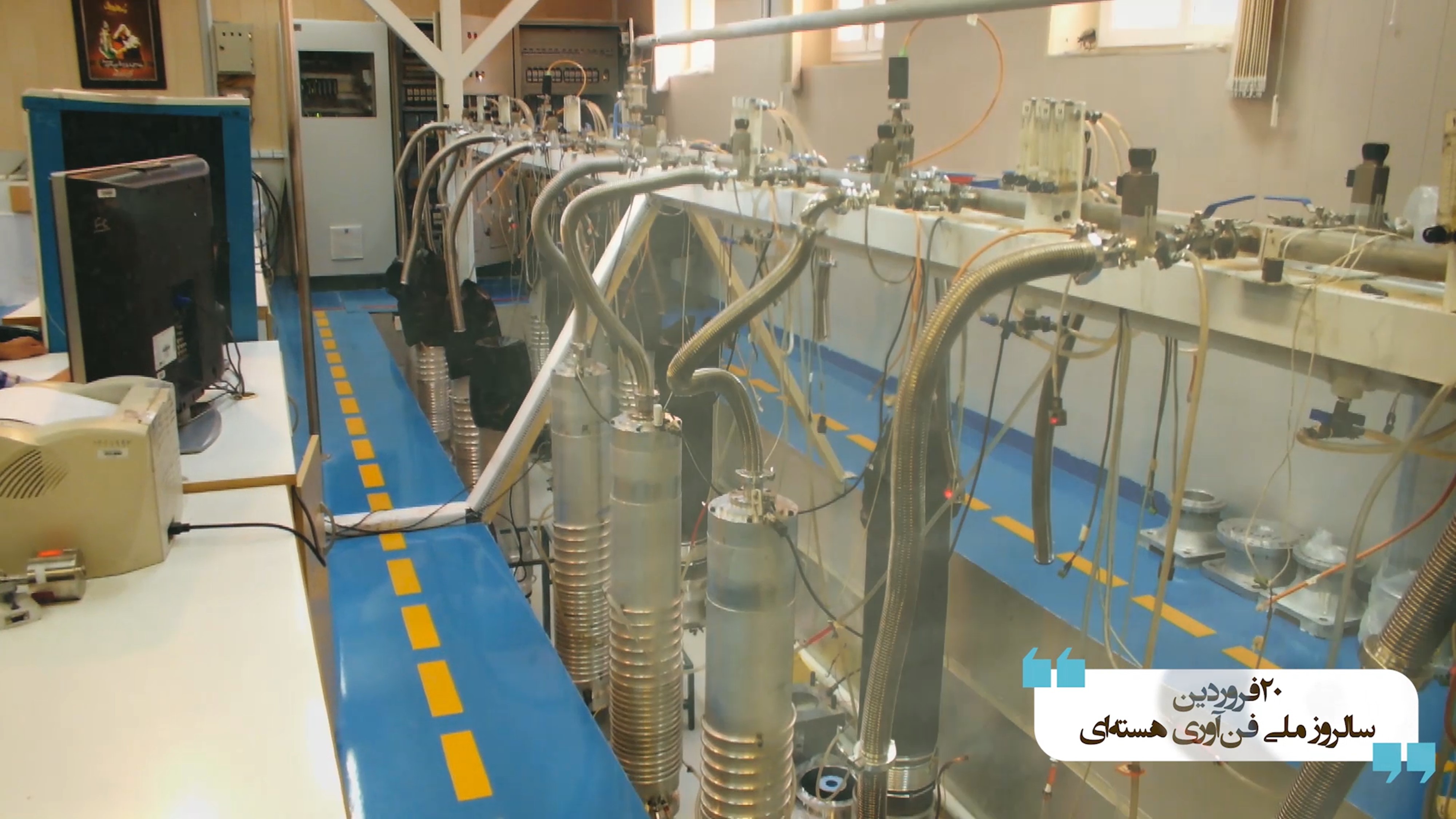
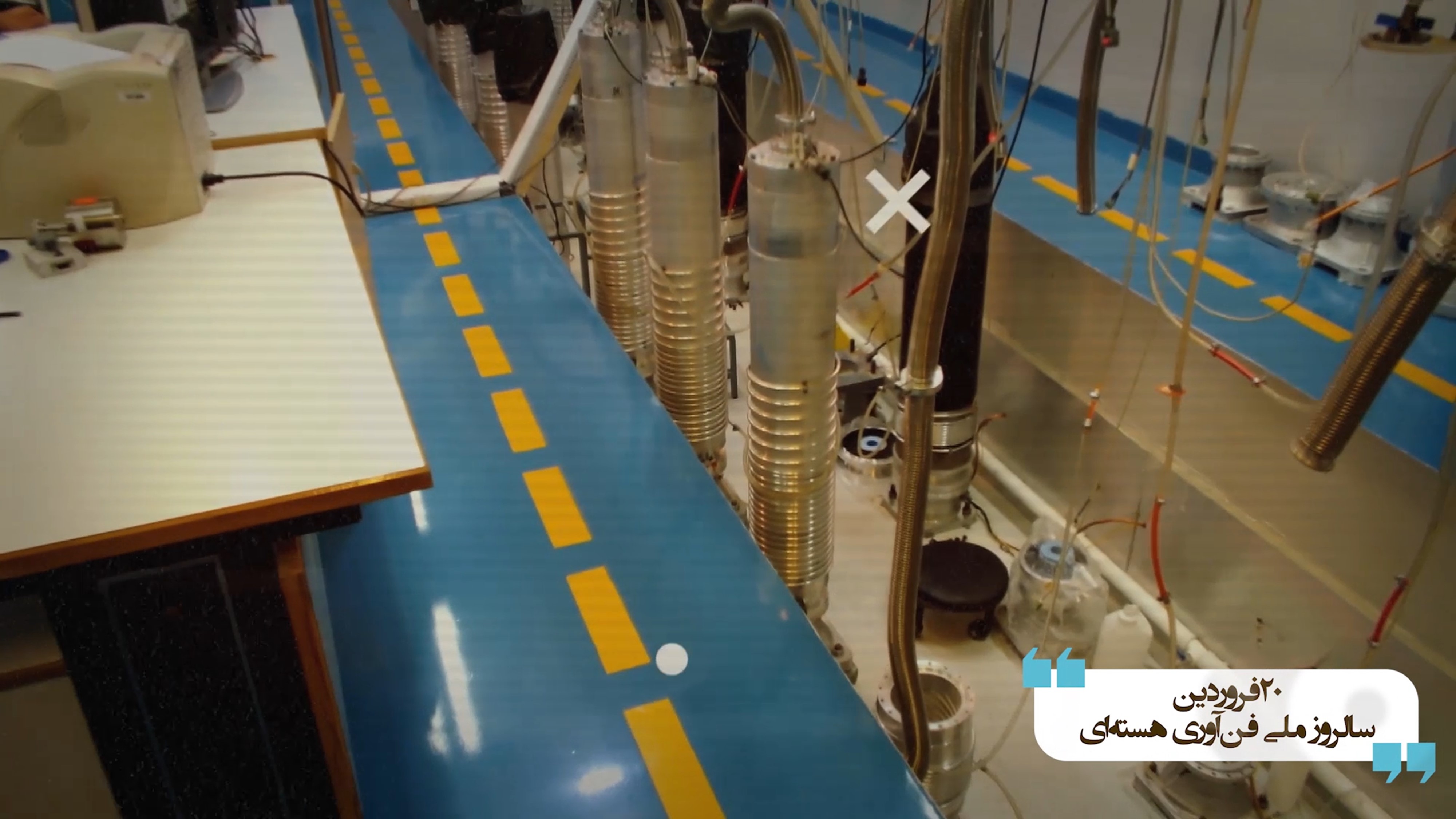
Figure 20. General views of advanced centrifuges in a pit, which looks different than the two discussed above. There are five or six IR-2m machines in the front row, all having metallic recipients and smaller in diameter. Several appear to be under vacuum and could be operating. Three others, with coverings, have the vacuum pipe unattached and may be on standby awaiting the insertion of new rotor assemblies. In the second row, visible is the possible installation and bolting of additional IR-6 centrifuge test stands. A motor housing with a motor inserted may be visible in the bottom photo on the bottom right. Stands of different diameters are visible in the lower right of the top photo and upper right of the bottom photo. Hand-operated vacuum valves are visible in the top image. The top photo has at least five sets of measuring or regulating devices, possibly for the water in the cooling cables.
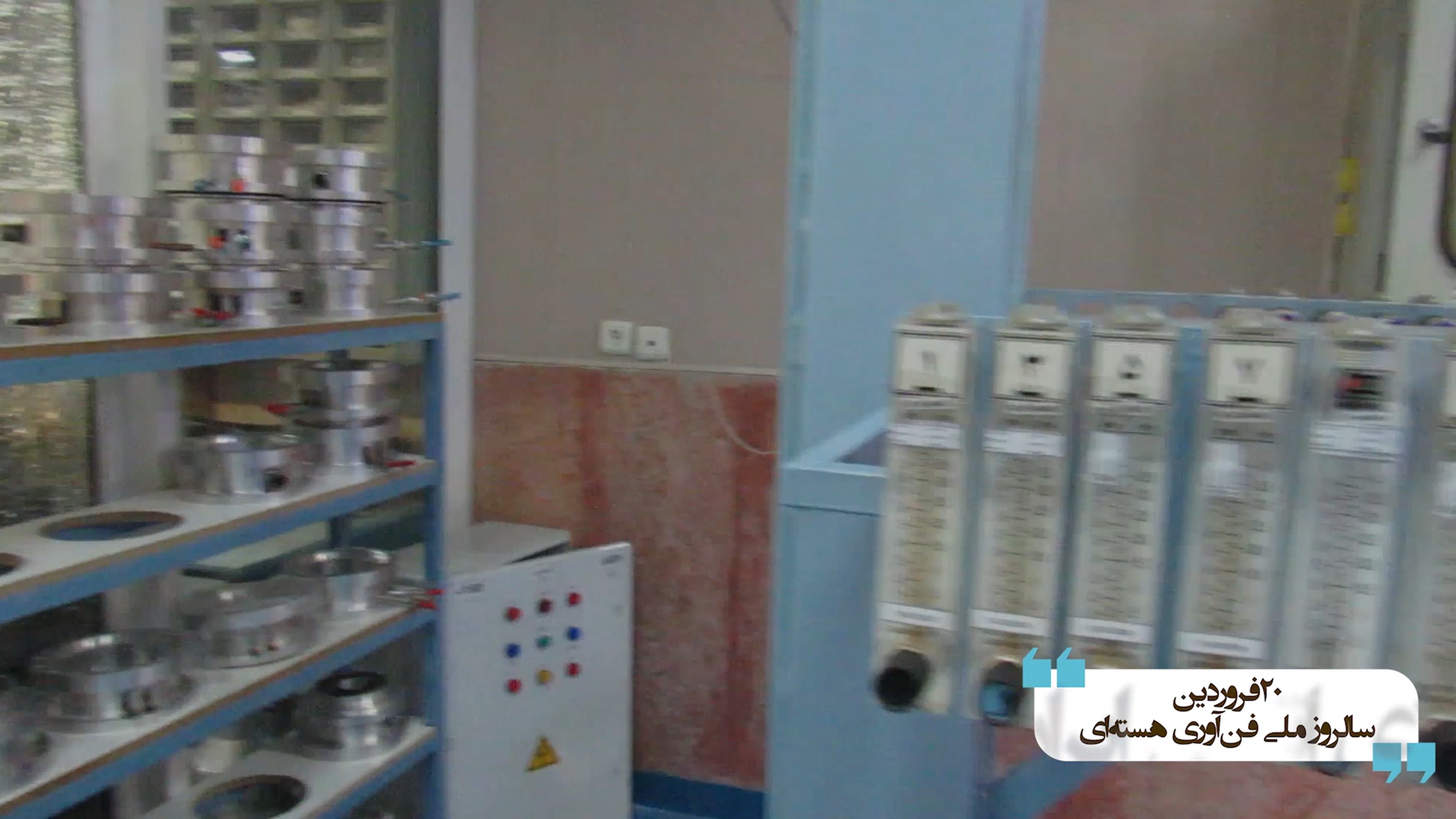
Figure 21. Visible are a number of components and subassemblies in the racks on the shelf. They may be motor housings, some with motors inserted. A pit may be visible behind the five monitoring or regulating devices
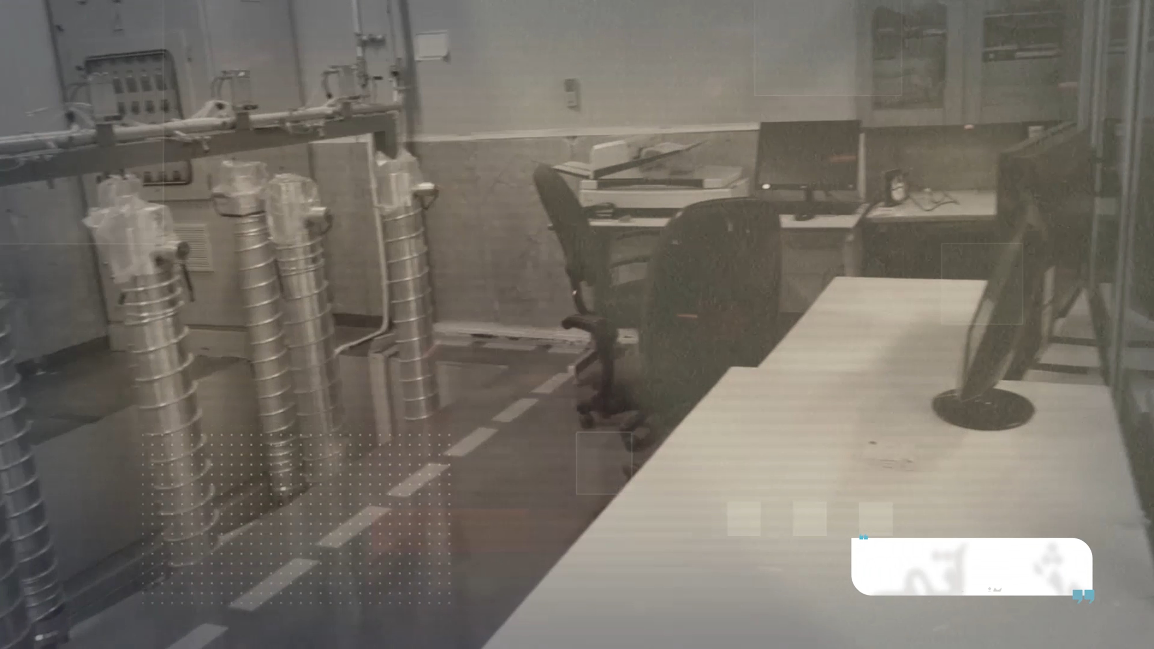
Figure 22. Based on their diameters and cooling cables, the centrifuge stands in the pit look to hold IR-1 centrifuge rotor assemblies. This pit may be a different one from the other three in earlier photos. For example, the overhead beam looks different from the others, and only one dotted warning line is visible. The test stands look to be on standby, consistent with the video’s narration.
1. “Analysis of IAEA Iran Verification and Monitoring Report - May 2022,” Institute for Science and International Security, June 6, 2022, https://isis-online.org/isis-reports/detail/analysis-of-iaea-iran-verification-and-monitoring-report-may-2022 ↩
2. David Albright and Sarah Burkhard, “Imagery Update: Iran Continues to Harden its New Natanz Tunnel Complex,” Institute for Science and International Security, May 5, 2022, https://isis-online.org/isis-reports/detail/irans-natanz-tunnel-complex-deeper-larger-than-expected/8. ↩
3. David E. Sanger, Julian E. Barnes and Ronen Bergman, “Fears Grow Over Iran’s Nuclear Program as Tehran Digs a New Tunnel Network,” The New York Times, June 16, 2022, https://www.nytimes.com/2022/06/16/us/politics/iran-nuclear-program-tehran.html. ↩
4. David Albright, Sarah Burkhard, and John Hannah, “Iran’s Natanz Tunnel Complex: Deeper, Larger than Expected,” Institute for Science and International Security, January 13, 2022, https://isis-online.org/isis-reports/detail/irans-natanz-tunnel-complex-deeper-larger-than-expected/8. See also, “Fears Grow Over Iran’s Nuclear Program as Tehran Digs a New Tunnel Network.” ↩
5. The video is available on the AEOI website and also on Youtube at https://www.youtube.com/watch?v=qP-TRHHbCzo. ↩
6. David Albright, Sarah Burkhard, and Spencer Faragasso, “A Comprehensive Survey of Iran’s Advanced Centrifuges,” Institute for Science and International Security, December 2, 2021, https://isis-online.org/isis-reports/detail/a-comprehensive-survey-of-irans-advanced-centrifuges/8; see also “Updated Highlights of Comprehensive Survey of Iran’s Advanced Centrifuges,” Institute for Science and International Security, March 17, 2022, https://isis-online.org/isis-reports/detail/updated-highlights-of-comprehensive-survey-of-irans-advanced-centrifuges/8. A finished IR-6 rotor assembly is composed of two rotor tubes, a bellows, a baffle, a top cap with a magnet, a bottom cap with a pin/ball attachment, and a motor armature. ↩
7. Indicating additional design changes in end caps post-2015, a Kalaye Electric exhibition booth at the April 2022 Nuclear Technology Day displayed a flat aluminum end cap in a relatively wide carbon fiber rotor tube. As part of JCPOA implementation, Iran declared that the IR-2m centrifuge had flat, high-strength aluminum end caps, but this rotor tube appears significantly wider than that of the IR-2m centrifuge. In the back of the exhibit, posters discuss “monitoring of centrifuge parameters,” the “improvement […] by changing the design,” and mentions specifically rotating parts and materials in connection with reliability. All of this may indicate that the design of key advanced centrifuges continues to evolve. ↩
8. “Analysis of IAEA Iran Verification and Monitoring Report - February 2021,” Institute for Science and International Security, February 25, 2021, https://isis-online.org/isis-reports/detail/analysis-of-iaea-iran-verification-and-monitoring-report-February-2021/8. ↩
 email us
 twitter